
3D obstacle detection of indoor mobile robots by floor detection and rejection
2013-12-20 07:22:27DonggeunChaWoojinChung
Donggeun Cha, Woojin Chung
(School of Mechanical Engineering, Korea University, Seoul 136-701, Korea)
3D obstacle detection of indoor mobile robots by floor detection and rejection
Donggeun Cha, Woojin Chung
(School of Mechanical Engineering, Korea University, Seoul 136-701, Korea)
Obstacle detection is essential for mobile robots to avoid collision with obstacles. Mobile robots usually operate in indoor environments, where they encounter various kinds of obstacles; however, 2D range sensor can sense obstacles only in 2D plane. In contrast, by using 3D range sensor, it is possible to detect ground and aerial obstacles that 2D range sensor cannot sense. In this paper, we present a 3D obstacle detection method that will help overcome the limitations of 2D range sensor with regard to obstacle detection. The indoor environment typically consists of a flat floor. The position of the floor can be determined by estimating the plane using the least squares method. Having determined the position of the floor, the points of obstacles can be known by rejecting the points of the floor. In the experimental section, we show the results of this approach using a Kinect sensor.
3D obstacle detection; mobile robot; Kinect sensor
CLD number: TP242.6 Document code: A
Obstacle detection is essential for mobile robots to avoid collision with obstacles. Mobile robots usually operate in indoor environments, where they encounter various kinds of obstacles.To detect these obstacles, various types of sensors are used in mobile robot applications.
The most widely used sensor in obstacle detection for mobile robots is 2D laser range finder (LRF), which senses only in 2D space. Therefore, 2D LRF is unable to detect obstacles when they do not exist in 2D plane.To solve this problem, one approach is presented to collect 3D range data by rotating a 2D LRF[1,2]. However, this method entails an extra cost for producing a mechanical structure, which is an addition to the high price of LRF. Another approach is to use a stereoscopic vision system to detect obstacles by obtaining a disparity image[3-5]. The disparity image can be obtained by using two individual cameras or by using a stereo vision sensor directly. When using two individual cameras for stereoscopic vision, the intrinsic parameters and the extrinsic parameters should be determined exactly to obtain accurate range data from 3D space. One more approach is to use a time-of-flight (TOF) camera, which is a 3D depth measurement sensor[6-8].
In this paper, we present a 3D obstacle detection approach that will help overcome the limitations of 2D range sensor with regard to obstacle detection. The indoor environment, where the mobile robot typically operates, consists of a flat floor. The position of the floor can be determined by estimating the plane using the least squares method. Having determined the position of the floor, the points of obstacles can be known by rejecting the points of the floor. In the experimental section, we show the results of this approach using a Kinect sensor[9], which is a depth measurement sensor that can provide a depth image.
1 3D obstacle detection
The indoor environment, where the mobile robot usually operates, typically consists of a flat floor. Taking this into consideration, we surmise that if a sensor is able to detect the floor, we can extract information about obstacles by rejecting the detected floor. The algorithm for detecting obstacles in 3D space is described as follows.
1.1 Characteristics of the plane as seen on a Kinect sensor
When we inspect the floor with a Kinect sensor, the points of the floor are found to be distributed as shown in Fig.1. A plane obstacle of 30 mm height is placed on the floor. The points of the floor are distributed from about -640 mm to -660 mm along z axis, and the points of the plane obstacle are distributed from about -600 mm to -620 mm along z axis. As shown in this figure, the points in the plane appear to be distributed along z axis with a normal distribution.
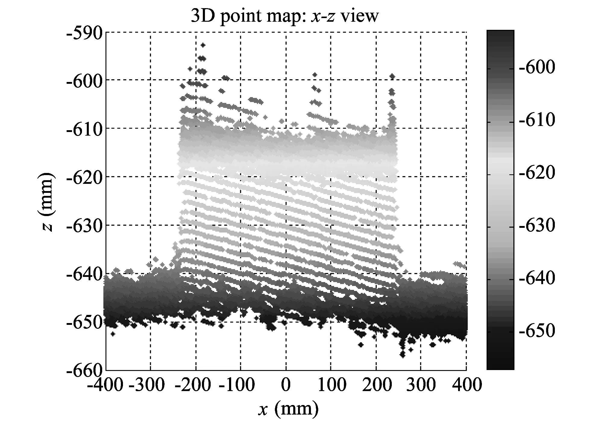
Fig.1 Points of a plane obstacle (30 mm height) and the floor, as viewed on a Kinect sensor (sensor's position: (0,0,0))
Based on this observation, we compares the distribution of points along z axis for plane obstacles with that of the observed floor. The comparison results are shown in Fig.2.
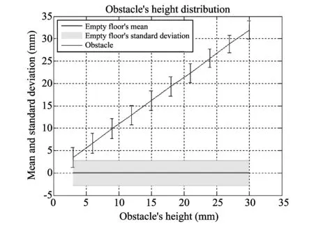
Fig.2 Distribution of points along z axis for plane obstacles and the floor
It can be seen from Fig.2, the average standard deviation is about 2.19 mm. Nearly all the points (about 99.7%) lie within 3 standard deviations of the mean. Therefore, if we set the threshold along z axis from the floor larger than 3 standard deviations, then we can find all the points in the floor.
1.2 Initial floor fitting
We begin with setting up an empty space in which there are no obstacles in front of the mobile robot, thus ensuring that the robot always moves around on a flat floor; the least squares method[10]is applied to looking for the plane of the floor for the empty region as shown in Fig.3. Assume that the plane's equation in 3D space {(x,y,z)} is


Fig.3 Preset environment in which there are no obstacles in front of the mobile robot
1.3 Obstacle detection
Elevation from the initially determined plane of the floor can be calculated for all existing points. By thresholding the elevation of each point, we can mark off all points in the floor and the obstacles as shown in Fig.4. The points within the floor are distributed from about -10 mm to +5 mm, and the points within the obstacle are distributed from +5 mm to +25 mm. Finally, the points of obstacles can be obtained by rejecting the points marked as the floor.

Fig.4 Elevation of points (Blue points: within the floor, Red points: within the obstacle)
2 Results and discussion
2.1 Experimental environment
A board and a portable desk are placed in the experimental environment, as shown in Fig.5(a). We apply the proposed method for obstacle detection to Kinect sensor's 3D point data, as shown in Fig.5(b). In this experiment, the threshold value along z axis from the floor for detecting points in the floor is set at 20 mm.
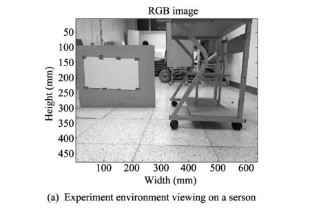
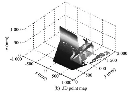
Fig.5 Environment for obstacle detection approach
2.2 Experimental results
The 3D point map of an experimental result is shown in Fig.6.
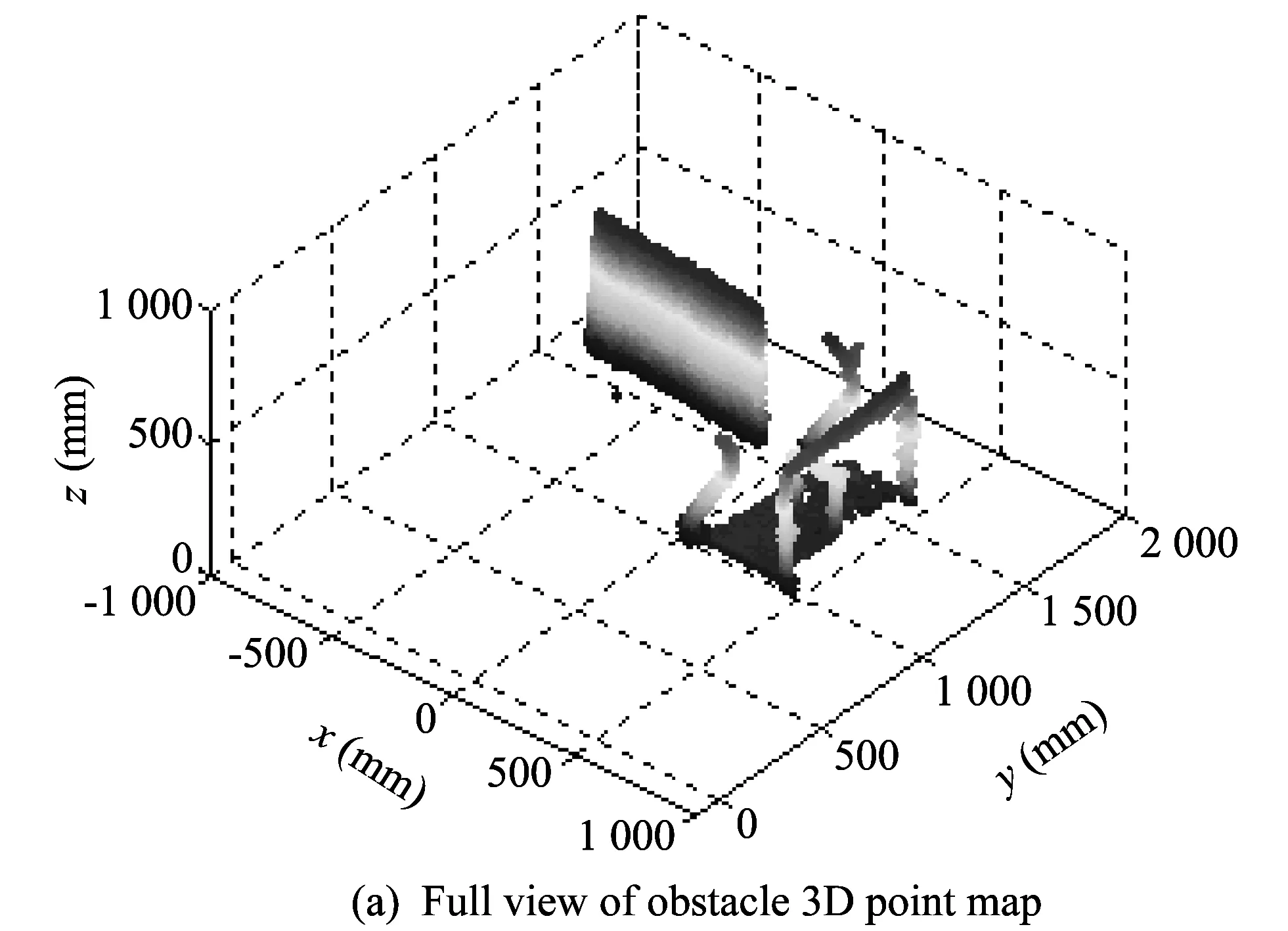
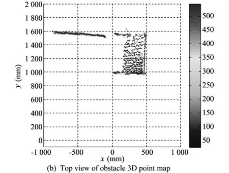
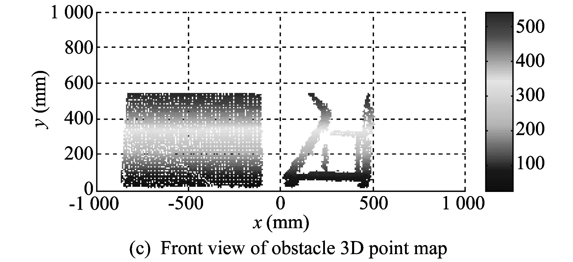
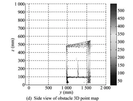
Fig.6 3D point data of experimental result
The points in the floor are rejected from the original 3D point data. An important element of the experimental result is the portable table. The results show that the table legs and a plate under the table, both of which may be detected by a 2D LRF, are detected as obstacles.
2.3 Discussion
The experiment is conducted in a static environment. For dynamic environments, a supplementary study is necessary to detect the position of floor by factoring in and making suitable allowances for the shaking of floor due to the movement of robots.
3 Conclusion
Obstacle detection is essential for enabling mobile robots to avoid collision with various obstacles. The proposed 3D obstacle detection approach can detect obstacles that may not be detected by 2D LRFs. Furthermore, we can obtain 3D point data of obstacles, which can be used in 2D maps by using x-y information collectively.
[1] Wulf O, Wanger B. Fast 3D scanning methods for laser measurement systems. In: Proceedings of International Conference on Control Systems and Computer Science, Bucharest, Romania, 2003: 312-317.
[2] Andreasson H, Triebel R, Burgard W. Improving plane extraction from 3D data by fusing laser data and vision. In: Proceedings of IEEE/RSJ International Conference on Intelligent Robots and Systems(IROS'05), 2005: 2656-2661.
[3] Labayrade R, Aubert D, Tarel J P. Real time obstacle detection in stereovision on non-flat road geometry through “v-disparity” representation. IEEE Intelligent Vehicle Symposium, 2002, 2: 646-651.
[4] Broggi A, Caraffi C, Fedriga R I, et al. Obstacle detection with stereo vision for off-road vehicle navigation. In: Proceedings of IEEE Computer Society Conference onComputer Vision and Pattern Recognition (CVPR'05), San Diego, CA, USA, 2005: 65.
[5] Broggi A, Caraffi C, Porta P P, et al. The single frame stereo vision system for reliable obstacle detection used during the 2005 DARPA grand challenge on TerraMax. In: Proceedings of IEEE International Conference on Intelligent Transportation Systems (ITSC'06), Toronto, Canada, 2006, 84: 745-752.
[6] Weingarten J W, Gruener G, Siegwart R. A state-of-the-art 3D sensor for robot navigation. In: Proceedings of 2004 IEEE/RSJ International Conference onIntelligent Robots and Systems(IROS'04), 2004, 3: 2155-2160.
[7] Droeschel D, Holz D, Stückler J, et al. Using time-of-flight cameras with active gaze control for 3D collision avoidance. In: Proceedings of IEEE International Conference on Robotics and Automation (ICRA/IO), Anchorage, Alaska, USA, 2010: 4035-4040.
[8] Holz D, Holzer S, Rusu R B,et al. Real-time plane segmentation using RGB-D cameras. In: Proceedings of the 15th RoboCup International Symposium and in RoboCup 2011: Robot Soccer World Cup XV, Springer, 2012: 306-317.
[9] Microsoft Co. Kinect for Windows. [2013-07-05]. http:∥www.microsoft.com/en-us/kinectforwindows/.
[10] Eberly D. Least squares fitting of data. Magic Software, Chapel Hill, North Carolina, 2000.
date: 2013-09-17
The MKE (Ministry of Knowledge Economy), Korea, under the ITRC (Information Technology Research Center) support program (NIPA-2013-H0301-13-2006) supervised by the NIPA (National IT Industry Promotion Agency); The National Research Foundation of Korea (NRF) grant funded by the Korea government (MEST) (2013-029812); The MKE (Ministry of Knowledge Economy), Korea, under the Human Resources Development Program for Convergence Robot Specialists support program supervised by the NIPA (NIPA-2013-H1502-13-1001)
Woojin Chung (smartrobot@korea.ac.kr)
1674-8042(2013)04-0381-04
10.3969/j.issn.1674-8042.2013.04.017
 Journal of Measurement Science and Instrumentation2013年4期
- Journal of Measurement Science and Instrumentation的其它文章
- A CAWL handler for context-aware composite workflow services
- Movement and behavior analysis using neural spike signals in CA1 of rat hippocampus
- Synthesis and cost estimation of ethylene oxide process using PRO/II
- Efficient model building in active appearance model for rotated face
- Preparation and characterization of TiO2-SiO2-Fe3O4 core-shell powders in nano scale
- Changes in hippocampal neural response by external reward