
Force-feedback based active compliant position control strategy for a hydraulic quadruped robot
2015-04-22 02:33:20WANGLipeng王立鵬WANGJunzheng王軍政MALiling馬立玲CHENGuangrong陳光榮YANGChaofeng楊超峰
WANG Li-peng(王立鵬), WANG Jun-zheng(王軍政), MA Li-ling(馬立玲), CHEN Guang-rong(陳光榮), YANG Chao-feng(楊超峰)
(Key Laboratory of Intelligent Control and Decision of Complex System, School of Automation, Beijing Institute of Technology, Beijing 100081, China)
?
Force-feedback based active compliant position control strategy for a hydraulic quadruped robot
WANG Li-peng(王立鵬), WANG Jun-zheng(王軍政), MA Li-ling(馬立玲), CHEN Guang-rong(陳光榮), YANG Chao-feng(楊超峰)
(Key Laboratory of Intelligent Control and Decision of Complex System, School of Automation, Beijing Institute of Technology, Beijing 100081, China)
Most existing legged robots are developed under laboratory environments and, correspondingly, have good performance of locomotion. The robots‘ ability of walking on rough terrain is of great importance but is seldom achieved. Being compliant to external unperceived impacts is crucial since it is unavoidable that the slip, modeling errors and imprecise information of terrain will make planned trajectories to be followed with errors and unpredictable contacts. The impedance control gives an inspiration to realize an active compliance which allows the legged robots to follow reference trajectories and overcome external disturbances. In this paper, a novel impedance force/position control scheme is presented, which is based on Cartesian force measurement of leg’s end effector for our hydraulic quadruped robot The simulation verifies the efficiency of the impedance model, and the experimental results at the end demonstrate the feasibility of the proposed control scheme.
active compliance; impedance control; force feedback; contact force; constrains space
Research on legged robots received much attention in the articulated robot fields in recent decades[1-3]. A legged robot with the capacity to evolve into versatile, multipurpose machine may eventually be very useful in many application scenarios such as disaster recovery, service robots, anti-explode events and military logistics. To achieve these tasks, the robot must be able to overcome the challenging terrain. The majority of existing researches employ high gain position control, which can achieve fast and accurate movement with a simple control mechanism in known environments[4]. When the task is involved contact with the environment as mentioned above, robots will try to satisfy the position goal with all available forces that may severely unbalance them. To achieve both fast robust locomotion and precise movements over unstructured and unknown terrains, different control approaches are required.
Trajectory tracking is needed when there is no physical counterforce from the external environment[5-6]. It’s better to actuate a swing leg as fast and precise as possible to place the accurate foothold. However, once the contact occurs that forces the leg into constraint space, the freedom dimensions will decrease and both robot and environment will be damaged if the impacts and crashes are too large. At this time, a compliance controller of dynamic behavior of the feet in case of physical interaction is desirable. It allows to behave either compliantly in case the robot hits an obstacle, or stiffly in case it has to locate on an object.
However, how to improve the compliant characteristics of legged robots in complex environments is still achallenge[7-8]. The model based traditional dynamic control methods need models for forward and inverse dynamics of robot and ambient environment[9]. It involves multi-rigid-body dynamics modeling, which will become more and more difficult when the freedom dimensions of legs increase. There are a lot of calculations and online measurements of the robot system, which will lead to a poor real-time performance[10]. What’s worse, the exact value of inertia matrix is hard to obtain because of the irregular shapes of leg parts.
1 Hydraulic quadruped robot
1.1 Platform overview
The experimental prototype of our hydraulic quadruped robot has 16 active DOFs and 4 passive DOFs, as shown in Fig.1. Each leg has hip-roll, hip-pitch, knee and ankle joints actuated by hydraulic cylinders which are self-designed and controlled by servo valves with high performance[11]. Each leg can be modeled as a 4-link mechanical system to generate endpoint trajectory. In this paper a 2-cycloid based zero impact foot trajectory generation method is proposed to reduce the disturbance force from the environment[12]. While the effect is limited on the floor with obstacles. Our recent research gives us a new inspiration on active compliance control. Because there are no tension and compression load cells in cylinders, our whole gait control is based on position control. So kinematics of robot will be presented firstly as follows.
1.2 Single leg workspace model
In order to plan the foot trajectory, the leg is modeled as a four-link mechanical system. Define the local reference coordinates and joint variableθi(i=1,2,3,4) for every revolution joint as shown in Fig.2. For notational convenience, the origin points of {Ji} are replaced by point R, P, K and A respectively for short. For lack of force sensors in cylinder, only the position control of cylinder is considered at present.

Fig.1 Hydraulic quadruped robot

Fig.2 Kinematic links structure with joints name
Combining Fig.1 and Fig.2, it’s easy to get the corresponding relationship between joint variableθiand related cylinder lengthlcyiin a mechanical triangle. Soθiis taken as a basic variable of kinematics in this paper. The kinematic equations of single leg in the operation space are
xJ2=sgn (leg)[l2cos (θ2)-l3cos (θ3-θ2)]+l4cos (π/2-θ5)zJ2=-l2sin (θ2)-l3sin (θ3-θ2)-l4sin (π/2-θ5)
(1)
(2)
whereJ2andJ1is {J2} and {J1} coordinates, respectively; leg is LF(left fore leg), RF(right fore leg), RH(Right hind leg), LH(Left hind leg);θ5is an auxiliary variable for calculating which is angle of friction cone[13].
To plan the foot trajectory in a gait, the trajectory generation method is represented here (for further details, refer to Ref.[12])
(3)
When planning out the P=[x,y,z]Tand referenceθ5in a leg’s coordinates, according above equations, it’s easy to get the inverse kinematic equation and control variable according the above equations as briefly described as
θ=T-1[PT,θ5]T
(4)
whereθ=[θ1,θ2,θ3,θ4]T. The actuated hydraulic cylinder lengthlcyican be calculated by the cosine law in the mechanical triangle.
2 Active compliance controller design
The conversion between the supporting phase and swinging phase of four legs according to a gait in turns composes the quadruped’s walking procedure. All the joints of our quadruped robot are actuated by hydraulic cylinders. As it is known, hydraulic actuated system has the advantages including fast output velocity and big driving force/torque. However, if a simple position control is applied to the quadruped robot out of laboratory environments, they will become hidden dangers of unbalance if feet hit an obstacle during swinging phase and the cylinders will give the maximum forces as possible as they can. So it’s very urgent to introduce a force control in a gait generation. In this paper, a position and force hybrid control scheme is designed for a single leg to achieve active compliance in force constrain space as is shown in Fig.3.

Fig.3 Block diagram of the position and force hybrid control scheme
As has been analyzed above, the three dimensional positions of a single leg can be actuated separately, that is, the endpoint position in the Cartesian space of a leg is freely controlled, although a single leg is a strongly coupled as a highly nonlinear system. Therefore, the impedance model of a single leg in vertical direction is presented at first, and thn it is extended to the three dimensions situation.
2.1 Position-based impedance force control model in vertical direction
Acommon aim of impedance model is simulated by a spring-damper system which is usually used in legged robots for passive compliance behavior. Suppose the Cartesian inertia is m, the stiffness isk, and the damping isd, the dynamical system is
(5)
Using Laplace transform, we have
(6)
If extern forcefis known, according the above equation, the end effector position can be easily figured out. Settingm=10 kg,d=60 N/(m·s),k=500 N/m, and applying an external step forcef=50 N (dashed line) andf=100 N (solid line) to the foot respectively, we obtain the following results as shown in Fig.4.

Fig.4 End effector impedance behavior under extern disturbance force
In other words, if the position is taken as a modified value for the planning trajectory when there are disturbances or contact forces, legs will have active compliance in a gait that will effectively reduce the damage to the robot. Inspired by the good performance of the impedance model, the leg controller can work with the same advantages when a sudden contact force occurs.
As summarized above, the endpoint work space changes from free Cartesian space to force constrained Cartesian space when there is an obstacle in a leg swinging procedure. Thus a selection mechanism is designed between the endpoint planning and the impedance control. The feedback forceffbdetermines the mutual inhibition selected scheme to chooseSeorS′e. WhenSeis selected, the foot trajectory generation method is used in the free Cartesian space until the end point detects a contact force. While in the force constrain space, the above impedance model is regarded as a filter and a supporting force closed-loop controller is designed. Taking the vertical locomotion as an example, the impedance equation is
(7)
wherefris the reference supporting force assigned by force distribution;ffbis the feedback contact force;zmodis the modified position value.
Using Laplace transform to the above equation and expressing the transfer function in block diagram form, the block diagram of force controller is shown in Fig.5.

Fig.5 Block diagram of the impedance force control scheme
2.2 Position-based impedance force control model of three dimensions
Single dimensional impedance force control is deduced. In a real walking gait of a quadruped, we need 2 or 3 dimension position servo of a leg. When there are contacts occurring suddenly, it will increase the risk of the robot instability if the same position control scheme is used in the force constrain space asthe Cartesian space. So it is very important to consider multidimensional force control.
We define the selected matrixesSeandS′ein the work space. When there are no contact forces,Seis an identity matrix andS′eis a zeros matrix. That means the swing leg is controlled by endpoint trajectory generation scheme in Cartesian space. While there are contact forces, the deflectionsfei(i=x,y,z) of reference contact forces and Cartesian measures determine the diagonal elements to be 1 or 0. Others are always zeros for the decoupling endpoint direction control. The diagonal elements ofS′ehave the completely opposite values withSe. The value 1 ofSemakes a single position control and the 1 ofS′eselects a modified position control as
(8)
wheregiis the function of above designed model.
3 Simulation experiment
The true prototype mechanism of our hydraulic quadruped robot is still under construction. In the simulations, we show a single dimension (vertical directionz) control result of the quadruped robot and a 2-dimension (horizontalxand verticalzdirections) result. Our simulation robot is 1.2 m long and 0.6 m wide and about 70 kg which is made of aluminum alloy. A single leg is about 9 kg heavy. So the impedance parameters arem=10 kg,d=60 N/(m/s) andk=500 N/m.
3.1 Force impedance control in vertical direction
It is supposed that the robot stands on an uneven terrain. The value of reference footholds in robot coordinates are LF -0.67 m, RF -0.69 m, RH -0.692 5 m, LH -0.695 m, and the start positions of each leg are -0.65 m, -0.689 m, -0.692 m, -0.693 m respectively. The control block diagram in Simulink is shown in Fig.6.
We use a simple force distribution method that makes the legs to equally share the gravity of the robot. The impedance control result of our system is shown in Fig.7.

Fig.6 Block diagram of the impedance force control for the quadruped robot in Simulink
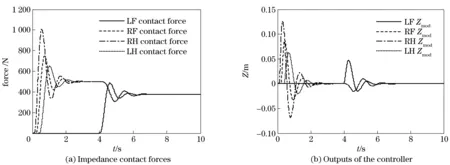
Fig.7 Impedance control results of four legs
3.2 Two dimensions endpoint trajectory impedance control in Matlab and Adams co-simulation
To demonstrate the feasibility of our control scheme shown in Fig.3, RF leg is considered as a fixed base system in Adams 2013 (see Fig.8). To assess the control effect of the proposed scheme, we ignore the spring in the foot, i.e. there is no passive impedance equipment in the leg.

Fig.8 Physical mechanism in Adams and the endpoint trajectory of control algorithm
Then the physical model is exported to Simulink of Matlab R2010b and the control scheme is programmed in m-file. The co-simulation block diagram is shown in Fig.9. The endpoint trajectory is generated according to Eq. (3) withS=0.3 m,H=0.2 m. Considering the fact that the horizontal direction obstacle makes worse damage to the balance, different reference contact forces are applied. The vertical reference force is given by force distribution. The result in work space is shown in Fig.8 in white curve and the contact forces under control measured at the endpoint in Adams are shown in Fig.10.

Fig.9 Control block diagram of co-simulation of Matlab and Adams in Simulink
The horizontal contact force in Fig.10 shows a good performance to attenuate the disturbance. The vertical force curve indicates the selection matrixes scheme work as expected and makes sure a good supporting of robot. The results in Figs.7, 8, 10 demonstrate the feasibility and effectiveness of the proposed scheme.

Fig.10 Contact forces of RF’s endpoint
4 Conclusions
In this paper, firstly a hydraulic quadruped robot is introduced. Then the work space of a single leg is analyzed in walking gait. To reduce the impact force in a walking gait, our previous work on endpoint trajectory generation is introduced. As the outdoor walking environment is generally unstructured and a single trajectory generation might cause the damage to the robot and surroundings, therefore an impedance force control scheme is proposed, which is based on our small-impact trajectory planning method. The simulation results show the feasibility of the impedance control law, and then the experiments data demonstrate that the robot could be activly compliant with the obstacles in Cartesian space with force constraints.
Impedance control can buffer the impact from the walking gait that effectively avoids the damage to the robot and environment. When contact occurs, however, the trajectory of endpoint is changed and, correspondingly, the footholds are passively selected. If there is an obstacle at the beginning of the swinging process, it will affect the gait seriously and may cause the unbalance of a robot.Thus the consideration of bionic reflection based on the endpoint force feedback is a promising research topic, which is the objective of our future work.
[1] Raibert M, Blankespoor K, Nelson G, et al. BigDog, the rough-terrain quadruped robot [C] ∥Proceedings of the 17th World Congress the International Federation of Automatic Control, Seoul, Korea, 2008: 10822-10825.
[2] Boaventura T, Semini C, Buchli J, et al. Dynamic torque control of a hydraulic quadruped robot [C] ∥2012 IEEE International Conference on Robotics and Automation (ICRA), Piscataway, NJ, USA, 2012: 1889-94.
[3] Claudio S. HyQ - design and development of a hydraulically actuated quadruped robot [D]. Genoa: University of Genoa, Italy and Italian Institute of Technology, 2010.
[4] Focchi M, Boaventura T, Semini C, et al. Torque-control based compliant actuation of a quadruped robot [C] ∥2012 12th IEEE International Workshop on Advanced Motion Control (AMC), Piscataway, NJ, USA, 2012: 6.
[5] Xuesong S, Yiping Y, Ying Z, et al. Trajectory planning and posture adjustment of a quadruped robot for obstacle striding [C] ∥2011 IEEE International Conference on Robotics and Biomimetics (ROBIO), Piscataway, NJ, USA, 2011: 1924-1929.
[6] Zucker M, Ratliff N, Stolle M, et al. Optimization and learning for rough terrain legged locomotion [J]. International Journal of Robotics Research, 2011, 30(2): 175-191.
[7] Jaehwan P, Jong Hyeon P. Impedance control of quadruped robot and its impedance characteristic modulation for trotting on irregular terrain [C] ∥2012 IEEE/RSJ International Conference on Intelligent Robots and Systems (IROS 2012), Piscataway, NJ, USA, 2012: 175-180.
[8] Zhang T, Wei Q, Ma H. Position/force control for a single leg of a quadruped robot in an operation space [J]. International Journal of Advanced Robotic Systems, 2013, 10(2): 323-330.
[9] Buchli J, Kalakrishnan M, Mistry M, et al. Compliant quadruped locomotion over rough terrain [C] ∥Intelligent Robots and Systems, 2009. IROS 2009. IEEE/RSJ International Conference on, 10-15 Oct. 2009, 2009: 814-820.
[10] Craig J J. Introduction to Robotics: Mechanics and Control (3rd ed) [M]. Upper Saddle River, NJ: Prentice Hall, 2004.
[11] Wang L P, Wang J Z, He Y D, et al. A dual-fuzzy pressure compensation based symmetric control scheme of single-rod electro-hydraulic actuator [C] ∥4th International Conference on Manufacturing Science and Technology, ICMST 2013, August 2013, Dubai, United arab emirates. Trans Tech Publications Ltd, 2013: 379-384.
[12] Wang Lipeng , Wang Junzheng, Wang Shoukun, et al. Strategy of foot trajectory generation for hydraulic quadruped robots gait planning [J]. Journal of Mechanical Engineering, 2013, 49(1): 39-44.
[13] Takemura H, Deguchi M, Jun U, et al. Slip-adaptive walk of quadruped robot [J]. Robotics and Autonomous Systems, 2005, 53(2): 124-141.
(Edited by Wang Yuxia)
10.15918/j.jbit1004-0579.201524.0418
TP 24 Document code: A Article ID: 1004- 0579(2015)04- 0546- 07
Received 2014- 03- 15
Supported by the National High Technology Research and Development Program of China (863 Program) (2011AA041002)
E-mail: wangjz@bit.edu.cn
猜你喜歡
少先隊活動(2021年5期)2021-07-22 09:00:08
音樂天地(音樂創(chuàng)作版)(2019年1期)2019-03-19 07:30:00
心聲歌刊(2018年1期)2018-04-17 07:22:57
文理導航·科普童話(2017年4期)2018-02-10 19:41:09
蘭臺內(nèi)外(2017年5期)2017-06-06 02:24:02
學生天地(2017年1期)2017-05-17 05:48:09
中國老區(qū)建設(2016年1期)2016-02-28 09:31:50
西夏學(2016年1期)2016-02-12 02:23:32
讀者·原創(chuàng)版(2013年3期)2013-02-24 01:35:08
中共黨史研究(2010年6期)2010-04-27 14:27:40
 Journal of Beijing Institute of Technology2015年4期
- Journal of Beijing Institute of Technology的其它文章
- Influence of shear sensitivities of steel projectiles on their ballistic performances
- Generalized ionospheric dispersion simulation method for wideband satellite-ground-link radio systems
- Multi-subpulse process of large time-bandwidth product chirp signal
- Factor-graph-based iterative channel estimation and signal detection algorithm over time-varying frequency-selective fading channels
- Nano-silica particles enhanced adsorption and recognition of lysozyme on imprinted polymers gels
- Similarity matrix-based K-means algorithm for text clustering