
Wideband and high-gain BeiDou antenna with a sequential feed network for satellite tracking
2023-11-06 06:15:02ZhuolinDENGZhongyuTIANChenheDUANPeiXIAOZhuLIUGaoshengLI
Zhuolin DENG ,Zhongyu TIAN ,Chenhe DUAN ,Pei XIAO ,Zhu LIU ,Gaosheng LI??
1College of Electrical and Information Engineering,Hunan University,Changsha 410082,China
2School of Physics and Electronics,Hunan Normal University,Changsha 410082,China
Abstract: BeiDou-3 navigation satellite system was officially opened in 2020.While bringing high-performance services to people around the world,the navigation system requires well-designed BeiDou antennas.In this paper,we propose a wideband circularly polarized high-performance BeiDou antenna.The antenna realizes wideband circularly polarized radiation through a four-port sequential feed network,and the phase imbalance of the feed network from 1.05 to 1.80 GHz is less than 7°.The manufactured antenna demonstrates a return loss of more than 13 dB and an axial ratio <3 dB over the entire global navigation satellite system (GNSS) frequency band.The right-handed circular polarization (RHCP) gain of the proposed antenna is greater than 4 dB in the GNSS low-frequency band and can reach more than 7.1 dB in the high-frequency band.Dimension of the proposed antenna is 120 mm×120 mm×20 mm,i.e.,0.54λo×0.54λo×0.09λo,where λo is the wavelength of the center frequency.The proposed antenna connected to a GNSS receiver has tracked 12 BeiDou satellites with C/N0 ratios of GNSS signals greater than 30 dB.Such a high-performance antenna provides a basis for high-quality positioning services.
Key words: BeiDou antenna;Wideband circularly polarized radiation;Four-port sequential feed network;Global navigation satellite system (GNSS) receiver;Satellite tracking
1 Introduction
With the official opening of BeiDou-3 navigation satellite system (BDS-3) in 2020,the BeiDou business has entered a new era of global service.As the terminal part of a global navigation satellite system (GNSS),the performance of the antenna directly affects the number of satellites tracked.An important feature of BDS is that it can provide navigation information at multiple frequency points and improve positioning accuracy combining multi-frequency signals.Therefore,considering the wideband characteristics in antenna design is a good option to improve the ability to track satellites (Tamjid et al.,2020).
BDS includes three frequency bands,B1,B2,and B3,with center frequencies of 1575.42,1176.45,and 1268.52 MHz,respectively.To reduce the signal attenuation in various environments and the Faraday effect caused by the Earth’s polar magnetic field,most BeiDou antennas use circularly polarized radiation.Therefore,designing circularly polarized antennas covering these three frequency bands is the key to achieving high-precision positioning.
Some multi-layer antennas are used to realize multi-band applications of navigation satellite antennas.Liu YT et al.(2016) proposed a novel antenna with probe-fed stacked rectangular patches that covers Global Positioning System (GPS) L1,Glonass (Russia) L1,BDS-1 L,BDS-1 BDS-2 B1,and BDS-2 B3 frequency bands.The different patch resonances of the antenna realize multi-band applications in different frequency bands.Although multi-layer antennas are suitable for multi-band antennas,because the process of tuning multiple frequency points is quite cumbersome and the circular polarization bandwidth of patches is narrow,it is difficult to control the axial ratio (AR) bandwidth of multiple bands.Therefore,it is more feasible and effective to design a broadband antenna to cover the three frequency bands of BDS.
There are many methods by which an antenna can realize circularly polarized radiation.Yang et al.(2019)appropriately modified the microstrip patch via truncated corners and an L-shaped slit to produce two degenerate modes with the same amplitude and orthogonal phase to form a good circularly polarized radiation.This single-feed method is used mainly to adjust the structure of the microstrip patch to change the current flow to form a circular polarization.The circular polarization formed by this method has a narrow band and is used mostly for single-and dual-frequency antennas (Lu et al.,2017;Zhang JD et al.,2017;Liu SH et al.,2019).
A sequential feed network structure is an important way to realize circularly polarized radiation.First,its ports can achieve stable power distribution and phase shift in a wide frequency band,so it can broaden the impedance band and AR band of circularly polarized patch antennas.This approach is an excellent choice for microstrip patch antennas.Second,a sequential feed network places no requirement on the polarization mode of the antenna unit.Even a linearly polarized antenna unit can achieve good circularly polarized radiation.For example,Sun et al.(2017) proposed a four-port feed network structure consisting of three Wilkinson power dividers and three broadband phase shifters.The four groups of signals outputted by this feed network configuration have the same amplitude and a phase difference of 90°,and the circularly polarized radiation formed has a wide AR band.A wideband feed network based on weakly coupled transmission lines proposed by Liu Q et al.(2017) realizes the feed of sequential phases at 2-6 GHz,and effectively enhances the circular polarization bandwidth.Similar four-port feed network structures were mentioned by Zhang ZY et al.(2013),Lin et al.(2018),and Qiu et al.(2020).
However,all these structures are placed on the same side of the dielectric board,making the feed network too large.Shortening the distance between the microstrip lines causes serious coupling effects and reduces performance.Therefore,we design a sequential feed network with a three-layer structure.The idea of our study was inspired by Shah et al.(2019),Zada et al.(2021),and Guo et al.(2022).The structure of “feed network+ground+feed network” greatly reduces the size of the antenna.The unique microstrip line routing method avoids mutual coupling of the microstrip line.The microstrip line maintains a high degree of symmetry to ensure that the main beam of the antenna is vertical.Simulation results show that the feed network has excellent performance.It has a more stable phase shift and smaller size than the previously released four-port feed network,and can be easily ported to other similar antennas.
In this study,we propose a high-performance BeiDou antenna with a wideband stable phase-shift feed network.An accurate phase shift between each port of the feed network is achieved through detailed modeling and simulation.Test results are consistent with simulation results.In addition,we build a GNSS receiver,which can obtain the number of real-time tracking satellites of the test antenna to evaluate the actual performance of the BeiDou antenna.Our antenna performs well in the GNSS experimental test.
2 Design of wideband feed networks for circularly polarized antennas
2.1 Structure and theory
In this study,we use a combination of a Wilkinson power divider and a phase shifter to design a wideband equal power distribution phase shifter,which can equally divide the input signal into four groups of output signals with a phase difference of 90°.The proposed feed network is composed of one 180° wideband phase shifter cascaded with two wideband 90°phase shifters.
The Wilkinson power divider can be regarded as a three-port network.The signal input at port 1 is divided into two signals,2 and 3,with the same amplitude and phase.An isolation resistorRis loaded between the two branches to improve the isolation.Assume that the impedanceZ0of port 1 is 50 Ω,andR=2Z0=100 Ω.If all three ports are ideally matched,the isolation resistors dissipate power.
The relationship between the phase and the microstrip line is Δφ=βl(βis the phase constant).The most direct way to change the phase is to adjust the length of the microstrip line,but this method makes the phase change with the frequency,which is not suitable for a broadband phase shifter.Therefore,how to reduce the sensitivity of phase shift to frequency is the focus of the broadband phase shifter.
As shown in Fig.1,the composition of the wideband phase shifter includes one Wilkinson power divider and one phase shifter.
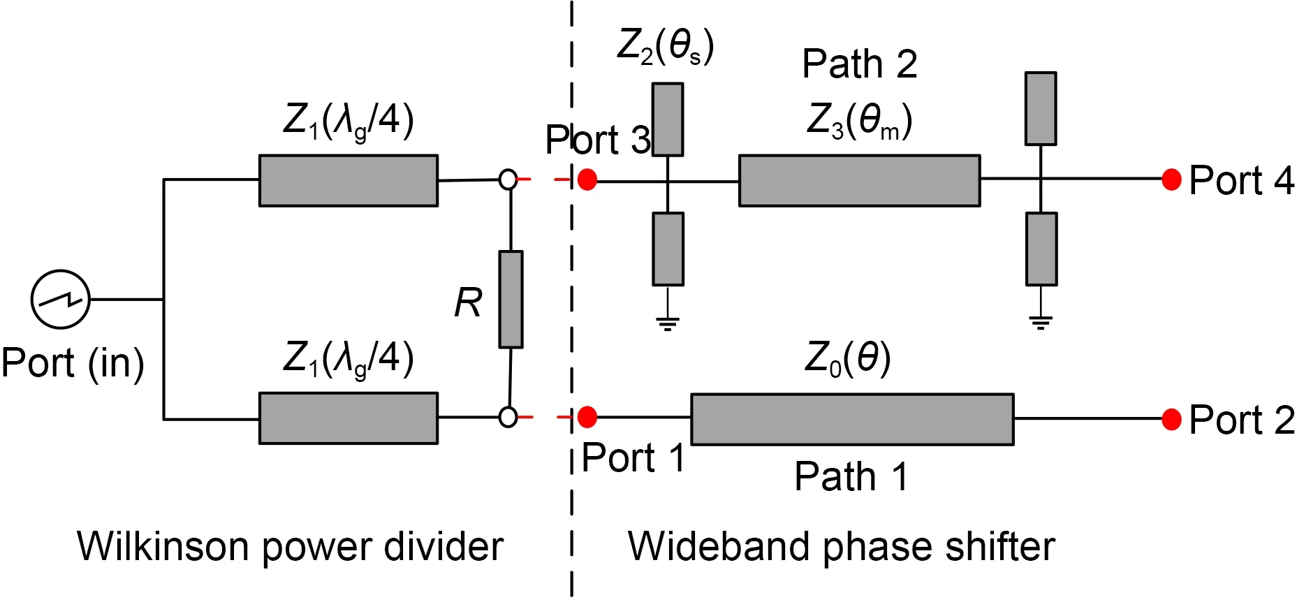
Fig.1 Combination of a wideband phase shifter and a Wilkinson power divider
The phase shifter is composed of two branches.Path 1 consists of a microstrip line with electrical lengthθand impedanceZ0.Path 2 contains a main microstrip line and two pairs of open and short stubs.The impedance and electrical length of the microstrip line and the stubs areZ3,Z2andθm,θs,respectively.The impedance of the four ports isZ0.
Compared with path 1,path 2 has more dispersed phase characteristics,and the phase slope can be regulated by the ratio of the main impedance to the stub impedance.This reduces the sensitivity of the phase shift to frequency and realizes a broadband phase shift.
Analyzing the structure of the phase shifter,theS-parameters to the two paths are given by
θm=are the normalized characteristic admittances,is the normalized frequency,t1andt2refer to the imaginary impedance of ports 3 and 4,and Δφ(f) is the phase difference between the two output ports.
2.2 Design of wideband feed networks
The desired phase shift and power distribution of the network can be obtained by proper determination ofZ3,Z2,Z1,Z0,andR.For case I,Δφ(f)=180°,with the design condition of voltage standing wave ratio VSWR=2 and the maximum phase difference within 5°,the relative bandwidth can theoretically reach 60%.We can obtain the impedance value of the microstrip line by Eqs.(1)-(5).
In Fig.1,the length of the microstrip line in path 1 in the 180° phase shifter isθ=λg,the length of the microstrip line in path 2 isθm=λg/2,and the lengths of the short and open stubsθsare bothλg/8.After calculation,we obtain the parameters as follows:
The layout of the 180° wideband phase shifter is shown in Fig.2.It is designed on Arlon AD450 substrate ofεr=4.5 with a thickness of 1 mm.Assuming that the center frequency is 1.4 GHz andZ0is 50 Ω,through Eqs.(6)-(9) we can obtainZ0,Z1,Z2,andZ3as 1.88,0.97,1,and 1 mm,respectively.The resistanceRis 100 Ω.
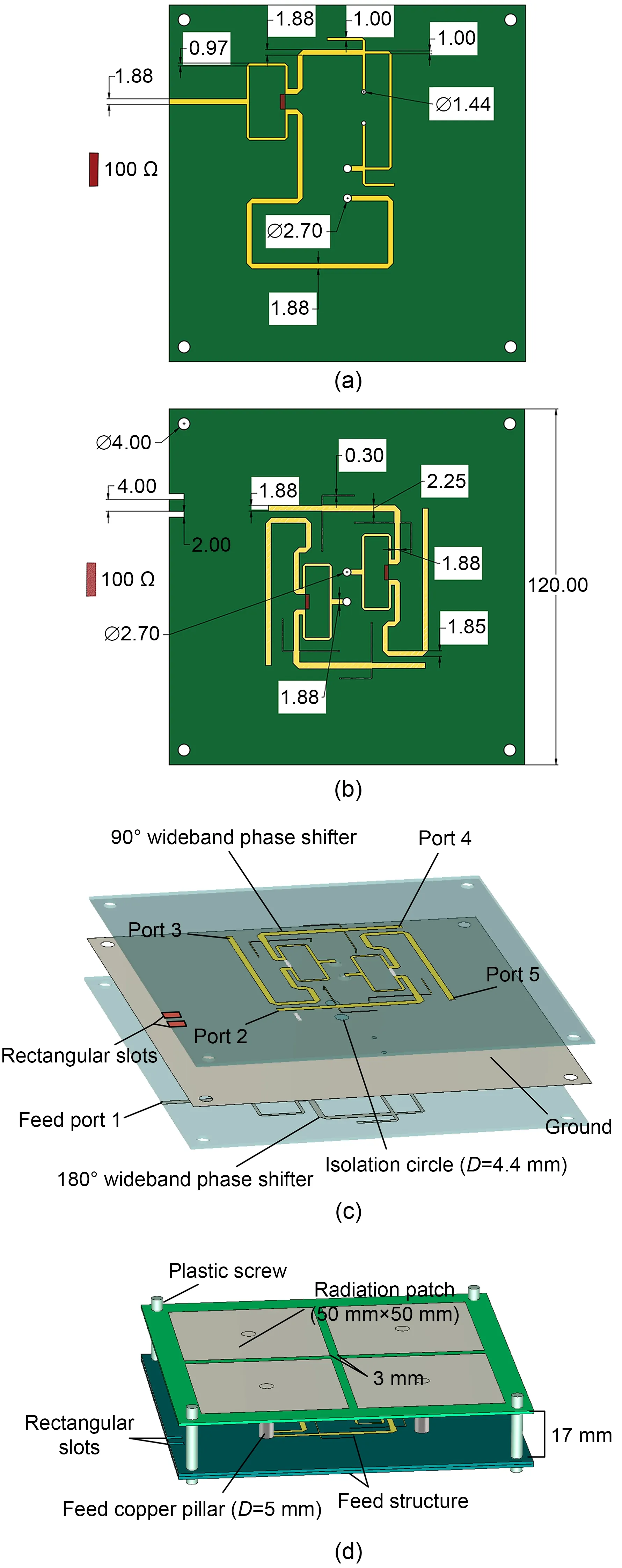
Fig.2 Schematic of the feed network: (a) 180° wideband phase shifter;(b) 90° wideband phase shifter;(c) feed net‐work;(d) geometry of the proposed antenna
For case II,Δφ(f)=90°,the analysis method is the same as the derivation of the 180° phase shift power divider.Due to the difference in phase shift,the values ofθ,θm,andθsare changed toλg/2,λg/4,andλg/8 respectively,and the value ofθsin Eq.(5) is changed to (π/2)fˉ.According to Eqs.(1)-(5),and by optimization through simulation,Z2andZ3are 2.19Z0and 0.9Z0,respectively.In the same substrate material,the widths of the microstrip lines are 0.3 and 2.25 mm.The layout is shown in Fig.2b,which shows two 90°wideband phase shifters.
To reduce the size of the antenna and increase the utilization rate of the substrate,we put the 180° phase shifter on the bottom layer and the 90° phase shifter on the upper layer,with the ground in the middle.The 180° phase shifter and 90° phase shifter are connected by a coaxial inner core (Fig.2c).Note that the two phase shifters are on two Arlon AD450 substrates,not on the front or back of one substrate.The two substrates are tightly joined by screws,so the height of the complete feed network is 2 mm.Fig.2c shows the short stubs connected to the ground through the probe.The 180° phase shifter is connected to the two 90° phase shifters through the coaxial inner core,and an isolation circle is etched on the ground to prevent the coaxial inner core from touching the ground.The diameter of each of the two coaxial inner cores is 5 mm,and the diameter of the isolation circle is 1 mm.Since the ground is in the middle of the substrate,it is not convenient to connect the SubMiniature version A (SMA)connector.Therefore,we add two rectangular slots at the edge of the upper substrate to expose the ground to ensure that the 50-Ω SMA connector could be welded.The rectangular slots are positioned directly above the bottom feed line (Fig.2c).
We use the combination of one 180° wideband phase shifter and two 90° wideband phase shifters to divide the input signal into four signals of equal power with a phase difference of 90°.The signal is fed to the patch through the coaxial cores to form circularly polarized radiation.Note that the placement of the two 90° phase shifters is related to the direction of rotation of the circularly polarized radiation.
We model and simulate the feed network in Computer Simulation Technology (CST) software.The results ofS-parameters are shown in Fig.3a.S11is clearly below -15 dB in the 1.05-1.80 GHz frequency band.The transmission parameters of each port are kept between 6.2 and 6.7 dB,and the energy difference between the ports does not exceed 0.5 dB.
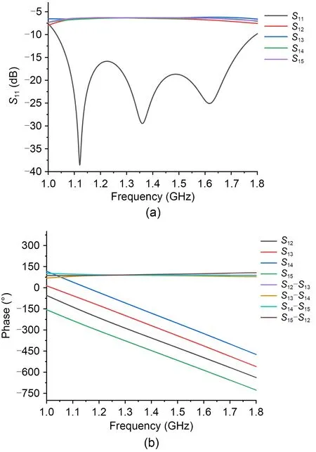
Fig.3 Simulation results of the feed network: (a) Sparameters;(b) phase difference between ports (References to color refer to the online version of this figure)
Fig.3b shows the phase difference between two adjacent ports.For example,S21is the phase value at port 2,andS21-S31is the phase shift value between ports 2 and 3.The phase of each port changes according to the same slope,and the phase difference between every two adjacent ports is maintained at about 90°.Phase imbalance varies by 7° throughout the operational band (1.05-1.80 GHz).
These simulation results show that the feed network has good power distribution and phase shift performance.Moreover,although many microstrip lines and probe structures have been added to the feed network,the design of the double-layer structure prevents strong coupling between the microstrip lines,thereby reducing energy loss and improving the performance of the feed network.
3 Wideband circularly polarized antenna design
In this section,a high-performance BeiDou antenna loaded with an optimized feed network is described.The antenna design details are discussed in Sections 3.1 and 3.2.
3.1 Design of a circularly polarized patch antenna
We originally planned to use a complete rectangular patch as our radiating part,but because the characteristic impedance of the entire rectangular patch did not match the feed network port,we considered using four symmetrical rectangular patches as the radiating part.The rectangular patch (Fig.2d) was designed on an Rogers RT5880 substrate ofεr=2.2 with a thickness of 1 mm.The size of each rectangular patch is 50 mm×50 mm,the spacing between the patches is 3 mm,and they are connected to the four ports of the feed network through a coaxial inner core with a diameter of 5 mm.The distance between the radiating patch and the feed structure is 17 mm,and the height of the air layer affectsS11and AR.The overall structure of the antenna is mechanically fixed by plastic screws at the four corners of the substrate.The plastic screws are made of polypropylene,and the dielectric constant (εr) is about 2.3 at 25 ℃.
3.2 Parametric study
Based on an extensive parametric study,the sensitive parameters of the antenna are the size of the rectangular patch (L),the diameter of the feed copper column (D1),the diameter of the isolation circle (D2),and the air gap (H) between the patch and the feed network.
Reducing the length of the patches shortens the current path on the patches,causing a significant decrease in gain.The gain becomes negative when the size of a patch is reduced to 35 mm×35 mm (Fig.4a).However,the patch size is too large to connect the four patches together,which not only reduces the forward gain,but also narrows the beam (Fig.5).Therefore,after detailed optimization ofL,we finally determined the optimum size of the patch to be 50 mm×50 mm.
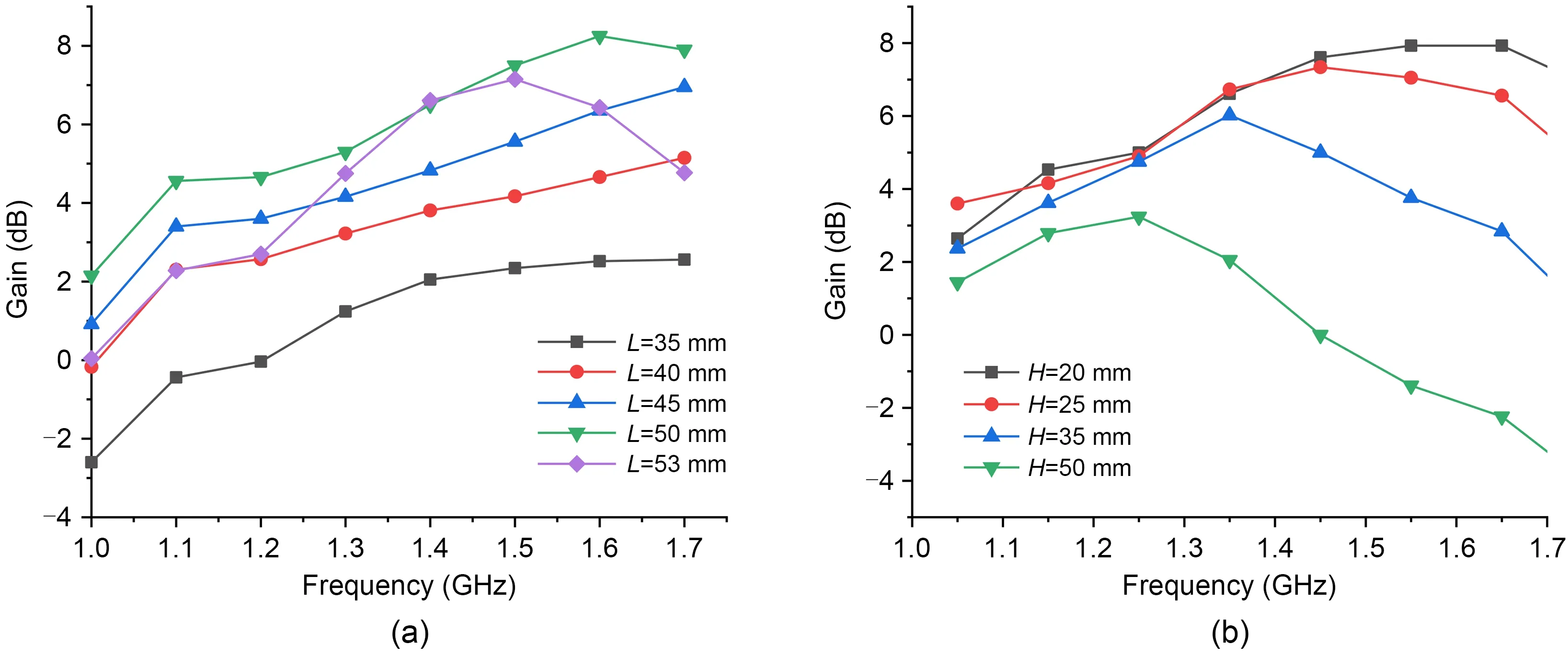
Fig.4 Frequency dependence of gain for a family of L (a) and H (b)
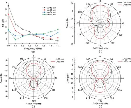
Fig.5 Axial ratios (ARs) at different H values (a) and simulated radiation patterns of the patch antenna at B1 (b),B2 (c),and B3 (d) (References to color refer to the online version of this figure)
We observe that the diameter of the isolation circle will affectS11.Fig.6a shows the behavior ofS11with differentD2values.In the B2 and B3 frequency bands,whenD2is greater than 4.4 mm,S11will become worse as the diameter increases,whileS11does not change within the range of 2.7 mm<D2≤4.4 mm.We believe that a too large diameter will destroy the integrity of the ground and affect the distribution of current,leading to a deterioration ofS11.Therefore,to ensure that the coaxial core does not touch the ground during welding andS11,we set the diameter of the isolation circle to 4.4 mm.The feed copper pillar is the bridge between the feed network and the radiating patch,and the diameter of feed copper pillar is related to the degree of matching.S11is best whenD1=5 mm (Fig.6b).
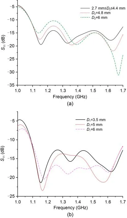
Fig.6 Frequency dependence of S11 for a family of D2 (a)and D1 (b)
The height of the air gap (H) affects the antenna gain and AR.Figs.4b and 5a present the gain and AR behaviors for different values ofH,respectively.Like the effect of a rectangular patch on the antenna,the height of the air gap affects the antenna gain:the larger theHvalue,the lower the forward gain.In the low-frequency bands (B2,B3),AR will increase with the increase ofH,while in B1,the increase inHwill cause the AR to deteriorate,and the impact on AR will be greater than 1 dB.
4 Experimental results
We built a prototype to verify the performance of the antenna.The front,side,and top views of the antenna are shown in Fig.7,and the whole unit was secured by four polypropylene screws.
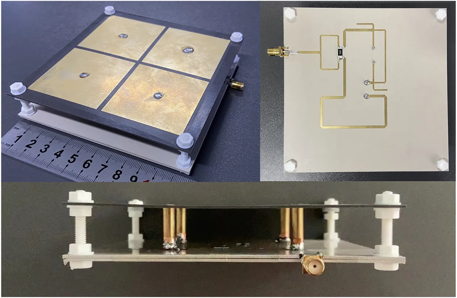
Fig.7 Prototype antenna
The reflection coefficient (S11) and AR are shown in Fig.8.The simulated and measuredS11values are both below -10 dB within 1.05-1.80 GHz,and relative bandwidth reaches 52.6%.The curves ofS11show a consistent trend,but the high-frequency resonance point is slightly shifted.The reason for the resonance point offset is that the copper foil with a thickness of about 0.1 mm is glued around the bottom of the feed copper pillar to strengthen the weld.The adhesion of copper foil changes the impedance of the copper pillar,and the air gap between the feed network and radiating patch makes the current at the bottom of the copper pillar discontinuous.This causes the resonance points of the simulated and measuredS11values to differ at high frequencies.
Although the measured and simulated ARs are generally consistent,the measured AR is about 0.5-1.0 dB higher than the simulated AR (Fig.8).This is due to fabrication errors in the welding of multiple components (probes and short stubs),and the adhesion of copper foil may also contribute to AR inconsistency.
Comparisons between measured and simulated gains are given in Fig.9.The measured antenna gain is 4 dB at the B2/B3 frequency bands,reaching 7.1 dB at B1.Insertion loss,fabrication imperfections,and addition of copper foils lead to a difference of about 0.7 dB between the measured and simulated gains at high frequencies.
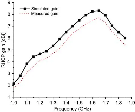
Fig.9 Simulated and measured gains of the proposed antennas (RHCP: right-handed circular polarization)
Fig.10 depicts the simulated and measured radiation patterns of the proposed antenna at 1176.45,1268.52,and 1575.42 MHz.The main beam pattern has good symmetry and is in good agreement with the simulation result.Half-power beam widths of the three patterns are all beyond 85°,which provides a guarantee for receiving satellites at low elevation angles.The backlobe of the beam is slightly distorted,but for the proposed antenna with a front-to-back ratio of more than 20 dB,this will not affect its actual performance.

Fig.10 Simulated and measured radiation patterns of the proposed antenna: (a) f=1176.45 MHz;(b) f=1268.52 MHz;(c) f=1575.42 MHz (RHCP: right-handed circular polariza‐tion;LHCP: left-handed circular polarization)
Measurement results of the proposed antenna are shown in Table 1.
We then compare the performance of our developed antenna with that of published antennas based on the parameters in Table 2.In terms of bandwidth,our proposed antenna has a wide impedance bandwidth and the AR bandwidth is larger than that of most GNSS antennas.Compared with Zhang ZY et al.(2013),our proposed antenna is superior in terms of right-handed circular polarization (RHCP) gain,with the highest gain of the proposed antenna being twice that of the antenna proposed in Zhang ZY et al.(2013).The antenna of Liu SH et al.(2019) also has high gain,but is larger than our antenna.
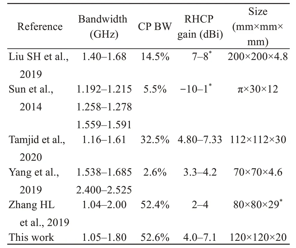
Table 2 Comparison of our proposed antenna with those proposed in other studies
In summary,although there are errors in fabrication and experimental processes,the measured AR andS11values of the antenna in the satellite frequency band are excellent,and the main beam pattern also shows good width and gain.This shows that our proposed antenna has high stability,and that the wideband circular polarization feed network has excellent performance.In the next section,we report the ability of the antenna to track satellites.
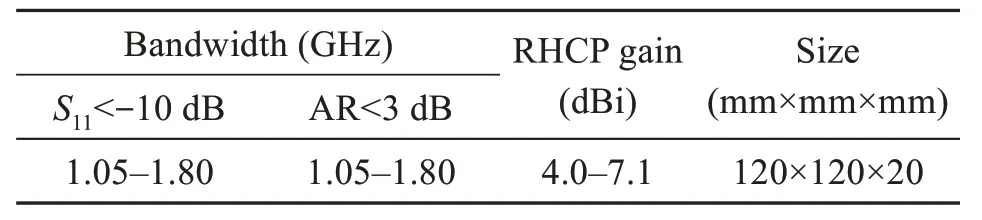
__Table 1 Measurement results of the proposed antenna
5 GNSS receiver experiments
To evaluate the overall performance of the antenna,the proposed antenna and a commercial BeiDou/GPS antenna were connected to a GNSS receiver for comparison.The receiver could receive signals from different elevation and azimuth angles,and could give the precise received carrier to noise ratio (C/N0) of each tracked satellite.Schematic of the GNSS signal reception experiment process is shown in Fig.11.The GNSS receiver we built is shown in Fig.12.It includes a GNSS module,a GNSS low-noise amplifier (GNSS LNA),and a USB-TTL.The USB-TTL converts satellite messages into a format that the computer can recognize,the GNSS LNA amplifies the received satellite signals,and the GNSS module solves the navigation messages to obtain the data of the antenna tracking the satellites.
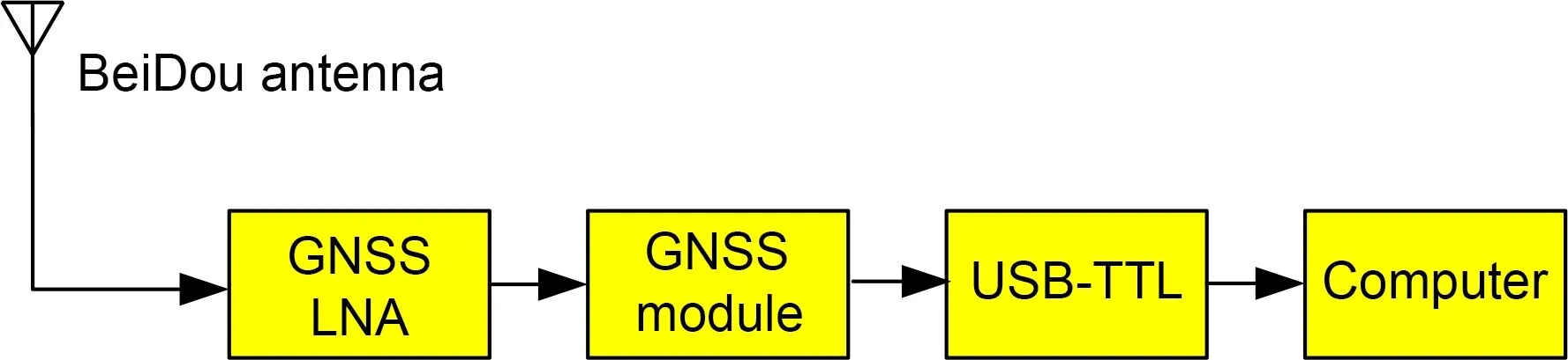
Fig.11 Schematic of the GNSS signal reception experiment process
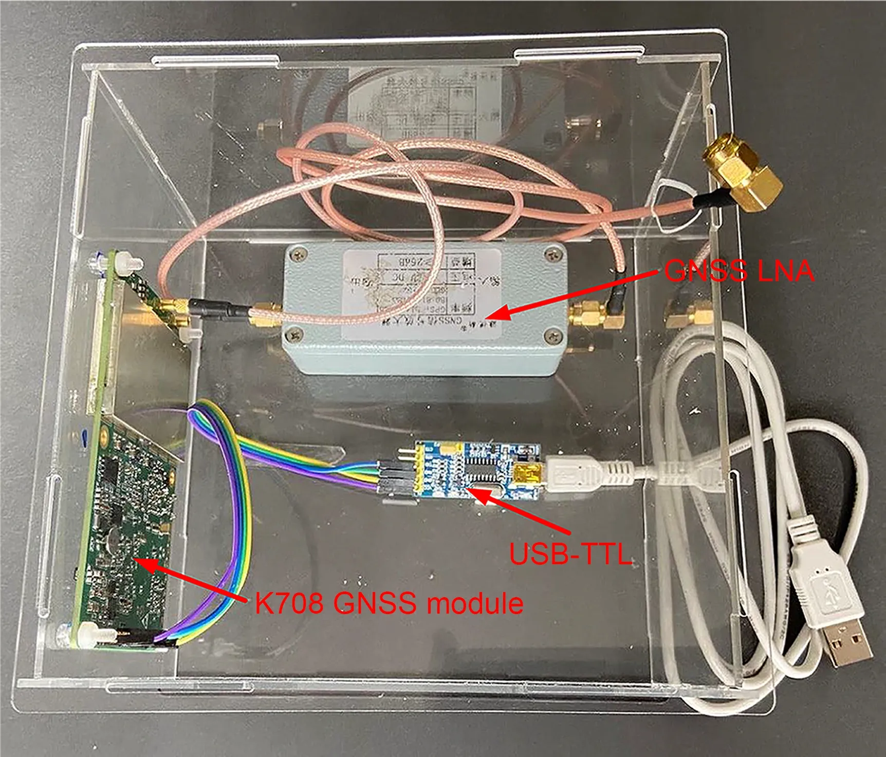
Fig.12 GNSS receiver
Since commercial satellite antennas have integrated GNSS LNA modules,we added a GNSS LNA to the proposed antenna to provide an effective comparison.The performance parameters of the GNSS LNA are shown in Fig.13.
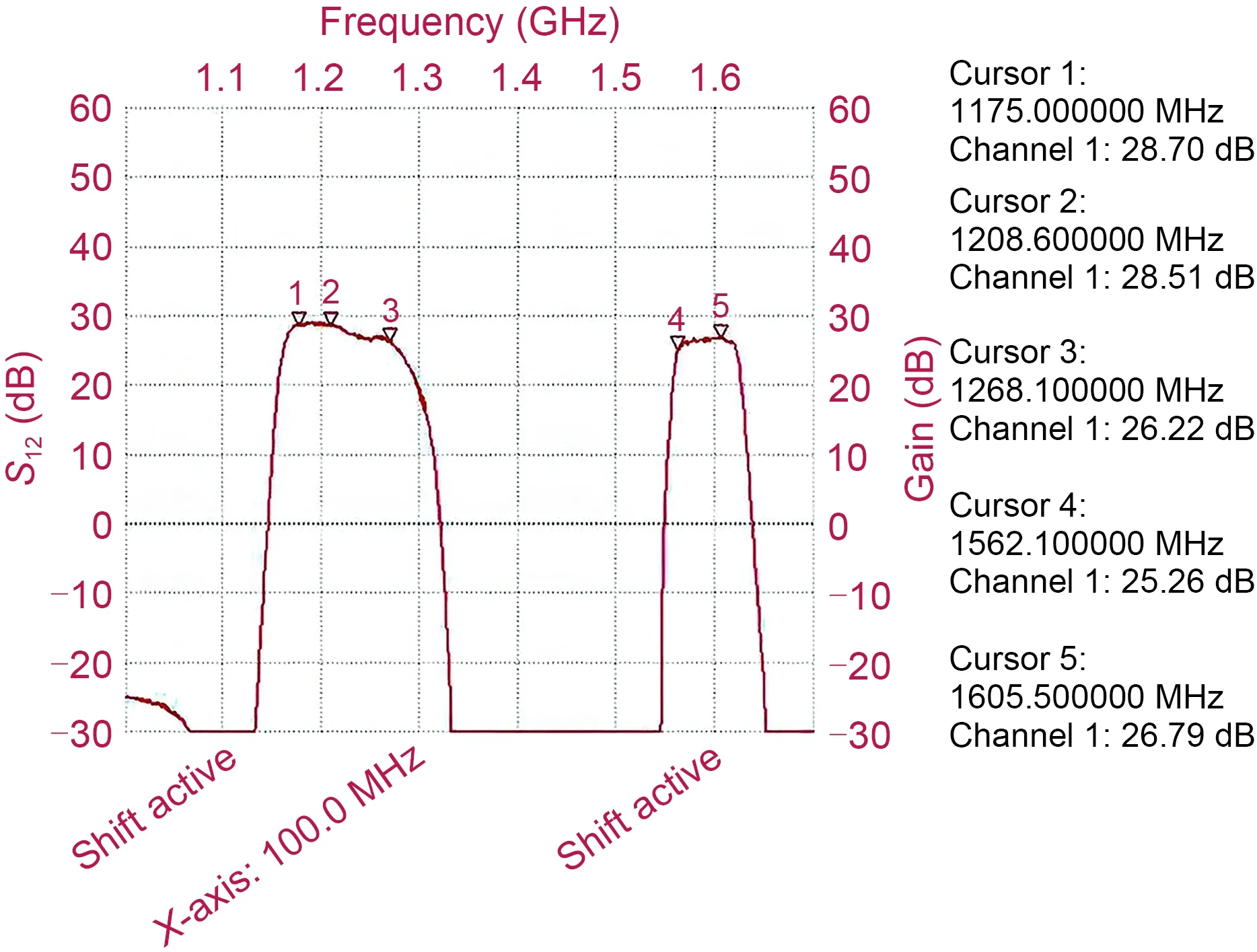
Fig.13 Performance parameters of GNSS LNA
Fig.14 shows the situation of tracking satellites.We found that our antenna could track 12 BeiDou satellites in the B1 frequency band (B1 and B1C),9 in the B2 frequency band (B2 and B2A),and 11 in the B3 frequency band.TheC/N0of all satellite signals is above 30 dB,which is an exciting experimental result.The results from tracking satellites of other GNSS systems (Fig.12),including four GPS (USA),five Glonass (Russia),and three Galileo (Europe) systems,show that our antenna performs well in other GNSSs.
A constellation plot of the tracked satellites is shown in Fig.15,in which the total number of tracking satellites has reached 24.Experimental results show clearly that our manufactured antenna has excellent performance,and a large number of tracked satellites can greatly improve the accuracy of positioning.Therefore,our proposed antenna has the potential to form the basis of a new generation of commercial BeiDou antennas.
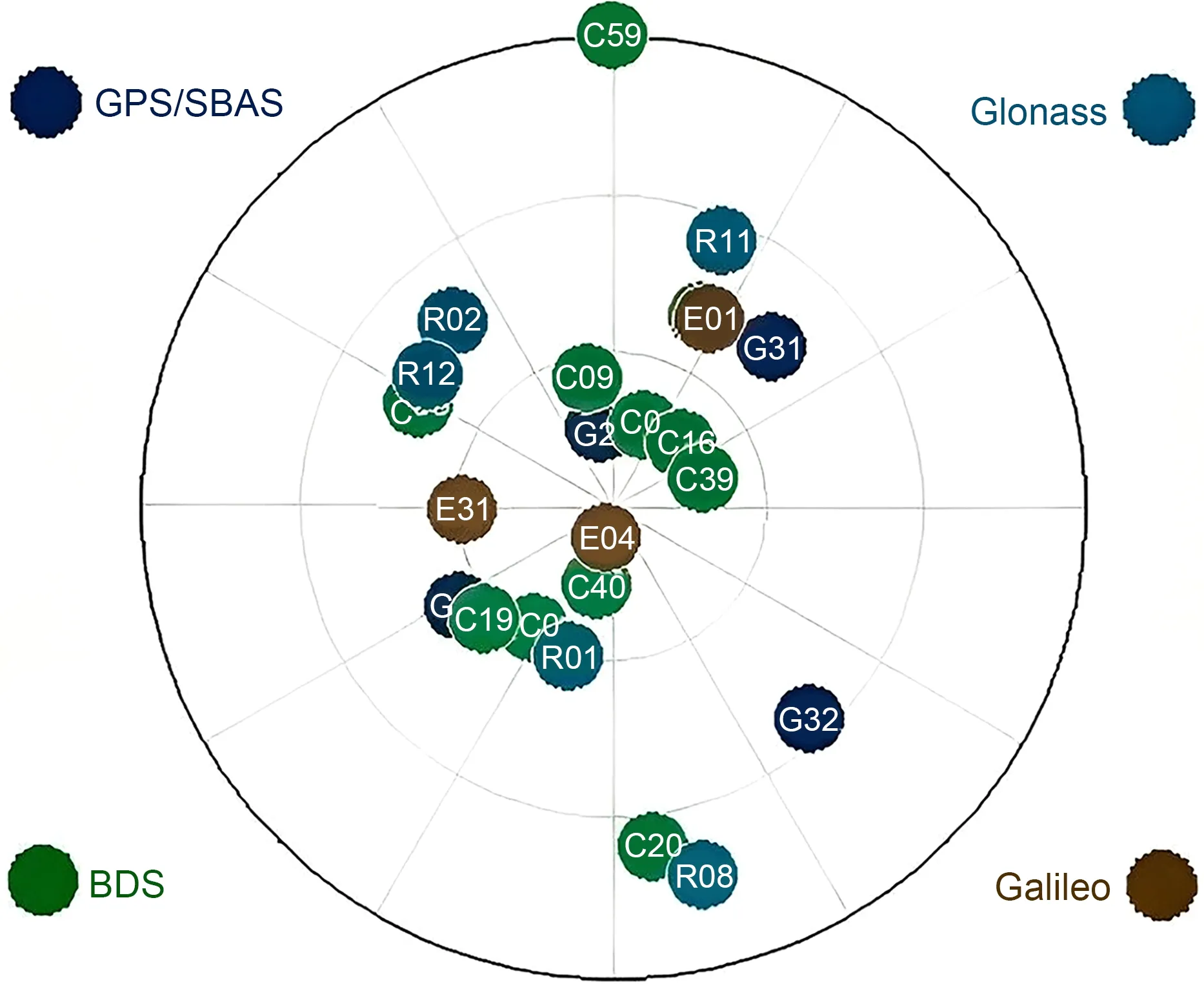
Fig.15 Constellation plot of the tracked satellites
6 Conclusions
The opening of the BeiDou-3 navigation satellite system has promoted the development of BeiDou antennas,and a wideband GNSS antenna loaded with a four-port sequential feed network was proposed.By analyzing the principle of the phase shifter,we designed a high-precision phase shift power divider with a phase imbalance <7° and a bandwidth that covers the entire GNSS frequency band.The main structure of the antenna uses four rectangular patches to achieve high gain.Measurement results show that the highest gain is 7.1 dB,which is higher than those of most microstrip GNSS antennas.The proposed antenna can track 24 satellites (12 BeiDou satellites) when connected to a GNSS receiver,and theC/N0is greater than 30.In short,the developed antenna could be a good candidate for BeiDou applications or other GNSSs.
Contributors
Zhuolin DENG designed the research.Zhongyu TIAN and Chenhe DUAN processed the data.Zhuolin DENG drafted the paper.Pei XIAO and Zhu LIU helped organize the paper.Zhuolin DENG and Gaosheng LI revised and finalized the paper.
Compliance with ethics guidelines
Zhuolin DENG,Zhongyu TIAN,Chenhe DUAN,Pei XIAO,Zhu LIU,and Gaosheng LI declare that they have no conflict of interest.
Data availability
The data that support the findings of this study are available from the corresponding author upon reasonable request.
 Frontiers of Information Technology & Electronic Engineering2023年10期
- Frontiers of Information Technology & Electronic Engineering的其它文章
- Correspondence:A low-profile dual-polarization programmable dual-beam scanning antenna array*#
- Correspondence:Uncertainty-aware complementary label queries for active learning?
- Path guided motion synthesis for Drosophila larvae*#
- Synchronization transition of a modular neural network containing subnetworks of different scales*#
- RFPose-OT:RF-based 3D human pose estimation via optimal transport theory?
- Attention-based efficient robot grasp detection network?