
Application of the Loading Inherent Subspace Scaling Method on the Whipping Responses Test of a Surface Ship to Underwater Explosions
2013-12-13 02:57:12LIUJianhuWUYoushengWANGHaikunPANJianqiang
船舶力學(xué) 2013年3期
LIU Jian-hu,WU You-sheng,WANG Hai-kun,PAN Jian-qiang
(China Ship Scientific Research Center,Wuxi 214082,China)
1 Introduction
It is well known that a nearby underwater explosion to a ship can cause the onboard equipments damage,hull rapture and whipping damage.Since 1950s,many naval architects had investigated the hull whipping effects of a ship induced by underwater explosion.Chertock[1]had set up a method for predicting the whipping responses of surface ship to underwater explosion based on mode superposition.Ma[2]had also used the similar method to investigate the whipping responses of a surface ship to underwater shockwave.Hicks[3]had developed Chertock’s method to use FEM modeling the ship structure.Li[4]had conducted an elastic scaled model of a surface ship to investigate the whipping responses to underwater explosion,and the experimental results are not suitable to convert directly to that of the prototype because the scale law are not clear.
Because the dynamics of underwater explosion bubble is strongly related to the gravity but the shock wave is not,there are some difficulties to achieve a complete similarity both in structural dynamics and in that of underwater explosion loadings in scaled model test.Lua[5]had proposed a‘big cover’method for modeling the hydraulic pressure of the ship bottom and the detonation position.This method is not easy to execute in reality.Schmidt[6]had used a geotechnic centrifuge to amplify the gravity of the model and the surrounding water for a subscale model to underwater explosion.Normally,if the pressure of the detonating position of the charge is not simulated,the geometric scale method can still be used to conduct the experiment to investigate the shock environment and local hull damage due to underwater explosion shock wave,and it is not suitable for modeling the whipping responses,as it is strongly relevant to the bubble loads that are seriously affected by the initial pressure of the detonation position.
The Froude scale method which is based on a dynamic similarity of the ratio between inertia and gravity force,is widely used in whipping model experiment caused by surface wave.In underwater explosion case,the shock wave energy must be balanced with the structural strain energy and the bubble dynamics must be balanced with the beamlike dynamic responses,and the Froude scale method can be used for whipping response modeling to underwater explosion with a scaled air pressure condition.Therefore,it is not easy to execute such an experiment for relative large model.In order to simulate the whipping responses of ship structure to underwater explosion in subscale,a scaled model test method has previously been proposed by Liu et al[7].This method does not like the geometric or Froude scale method that need to pressurize or decompress for free surface and have similar law in all mechanical space,and there is similarity between prototype and scaled model only in a load inherent subspace.This method is called Loading Inherent Subspace(LIS)scale method.The LIS scale method satisfies the subscale requirement by keeping the same ratios of the lower vibration mode periods to the pulsation periods of the bubble,and of the maximum radius to the detonation distance as the real ship situation to underwater explosion.And the method ignores the effects of the differences of the rising height of the bubble between scaled model test and the real ship situation.
In this paper,the LIS scale method is applied to a surface ship-like model,and both the prototype and the subscale model to underwater explosion were experimented.The whipping responses are measured respectively and compared to each other.It was also found that the damping coefficient varies with the amplitude of the responses and has important effects to the maximum bending moments.
2 Scale law and the experimental model
2.1 Scale Law
As usual for the low frequency modes of hull vibration,a simple beam model has been used to represent the elastic character of hull and the structure details of each section are not simulated.The mass distribution and the wet surface are simulated in scale method.If we design a model test with a scaled factor λl,we can get the relationship of the whipping response between the prototype ship and the model to underwater explosion from the LIS scale method.Results of main scale factors from the Ref.[7]are summarized in Tab.1.
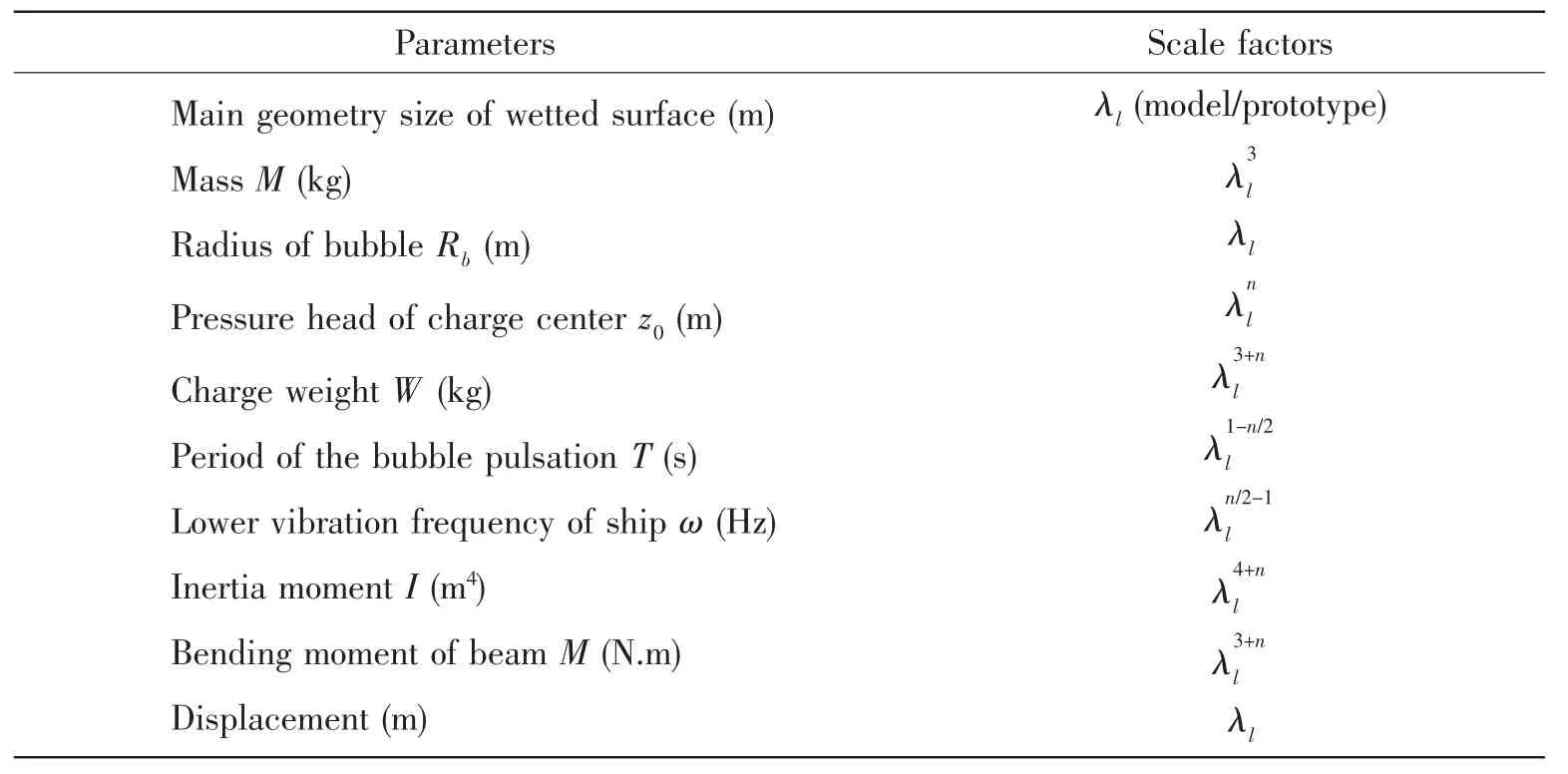
Tab.1 The summarized scale factors of model tests[7]
In Tab.1,the index n is a key value in the LIS scale method,as n constrains the similar space and it can be expressed as follows:
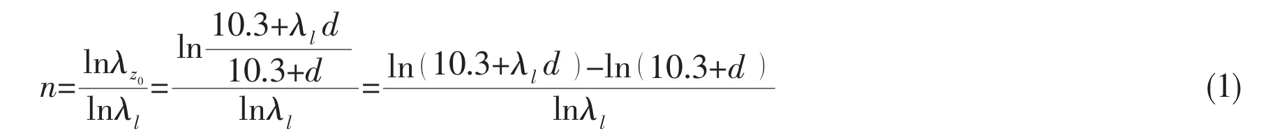
In above equation,d is the detonation depth of the charge.In usual condition,it can be seen that:0<n<1.This Loading Inherent Subspace(LIS)scaling method is different from the traditional existing scale methods.Every scale model has an unique scale index n that is relevant to the underwater explosion situation and it can only model some special load cases and not suitable for all cases.The geometric scale law requires n=0.The traditional whipping model test requires Froude numbers invariant and then n=1.In traditional scaling cases,the scaled model is only determined by the geometric scale factor λland is not inherent with the loadings of the prototype.
2.2 Experimental models
In order to validate the scale law,two models of ship whipping responses to underwater explosion are developed,where the big one acts as the prototype and the small one as the subscale model.Three-dimensional rendering of two models is shown in Fig.1.The main structure and half breadth plan of the prototype and the scale model are shown in Fig.2.It consists of 8 segments that are connected by 7 elastic cylinders.The 8 segments consist of the shiplike outlines and the main weight,and the 7 cylinders supply the bending stiffness of the beam that also act as the bending moment measuring meter by measuring the strain.There are 7 sealing rubber strips between segments.Ship lines of models are the same and satisfy geometry scale.
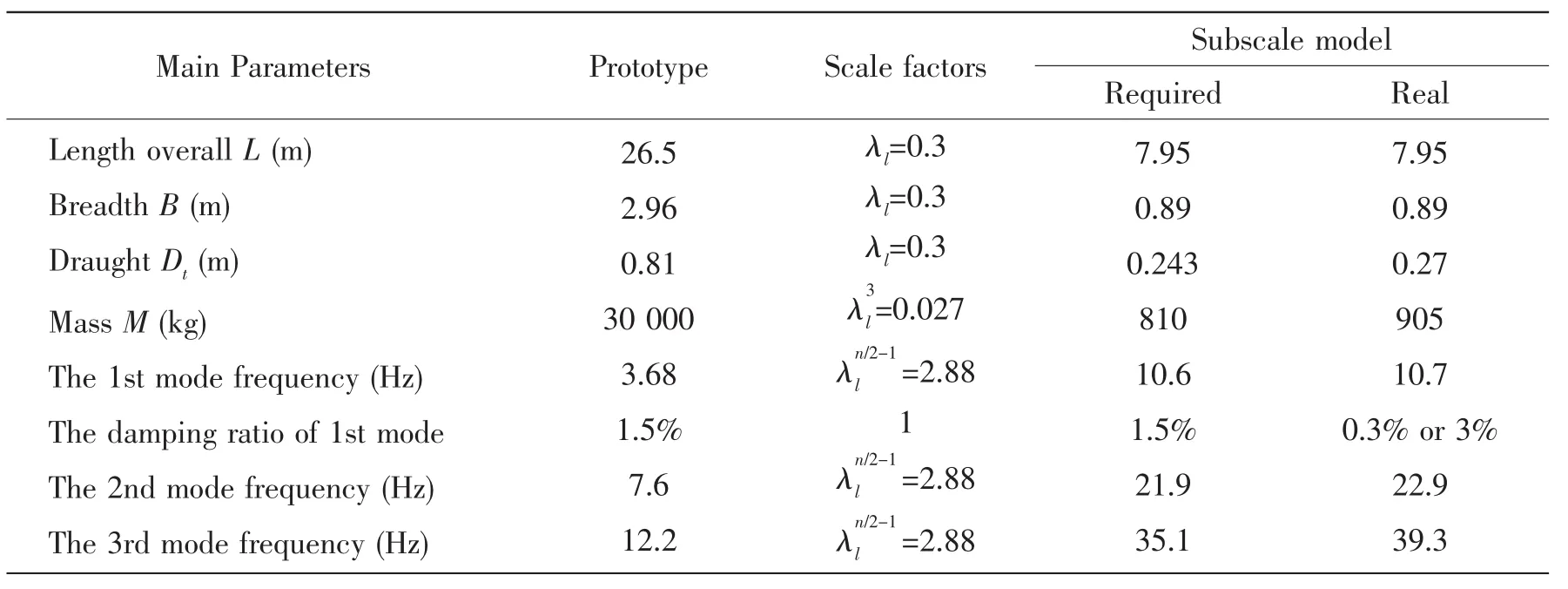
The subscale model is designed to simulate the prototype with a scaled factor of 0.3 and a scaled index n=0.244 3,and both the main structure stiffness and the mass distribution are similar with those of the prototype,and their manufacture techniques are the same.The main parameters of the prototype and the subscale model are listed in Tab.2.The inertia moment and segments mass both of the prototype and the subscale model are listed in Tab.3.The first vibration mode frequency is almost similar to the prototype,and there are some bias between the required and the real frequency of the second and third mode.However,the critical damping ratios are difficult to keep the same even if the technique of making the model is the same.The critical damping ratio of the first vibration mode initially is 0.3%that is much lower than that of the prototype.After damping treatment,the relevant ratio becomes 3%that is near to the value of 1.5%of the prototype.

Fig.1 Three-dimensional longitudinal cutaway view and fitting partial view of models
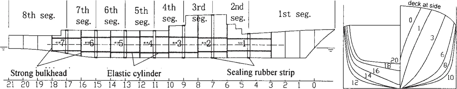
Fig.2 Structure and half breadth plan both of prototype and model
Tab.2 The key parameters of the prototype and the subscale model
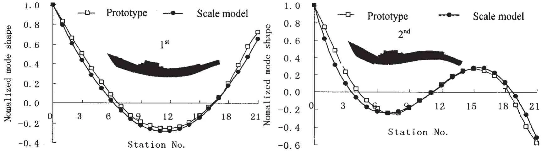
Fig.3 shows the first and second vibration mode shapes of the subscale model and the prototype,where curves obtained from vibration mode test are all normalized by the maximum to 1.Fig.4 shows the comparison of the normalized mode moment which was also obtained from vibration mode test between the model and the prototype.It can be seen that a good consistency is achieved on the mode parameters between the subscale model and the prototype,which is the base of getting good simulation results by scaled model test.Fig.5 shows the test scene of the prototype and 0.3 scale model to the underwater explosion,and it shows that the whipping responses had caused the water splashing in the aft and the stern.
Cylinders No.proto Itny ep re t i a moment(m m 4o)d elSegments No.protot Sy ep ge ment mass(k m g)odel 1234567 3.25E-03 4.96E-03 6.65E-03 6.72E-03 5.80E-03 4.76E-03 3.12E-03 1.967E-05 2.975E-05 4.016E-05 4.078E-05 3.543E-05 2.885E-05 1.876E-05 12345678 4 296 3 527 3 685 4 507 3 742 3 061 2 732 4 394 155 102 99 116 97 86 83 168
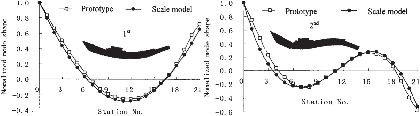
Fig.3 Comparison of test mode shapes between model and prototype
Tab.3 Inertia moments and segment mass of the prototype and the subscale model
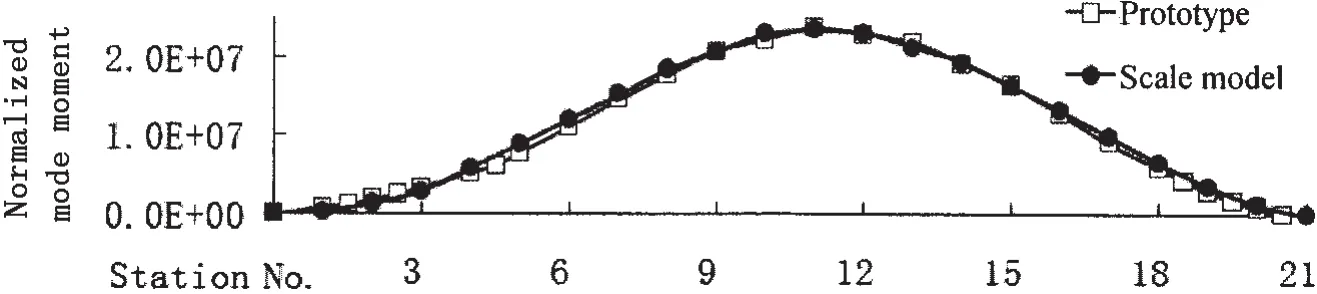
Fig.4 Comparison of test mode moments of the model and the prototype
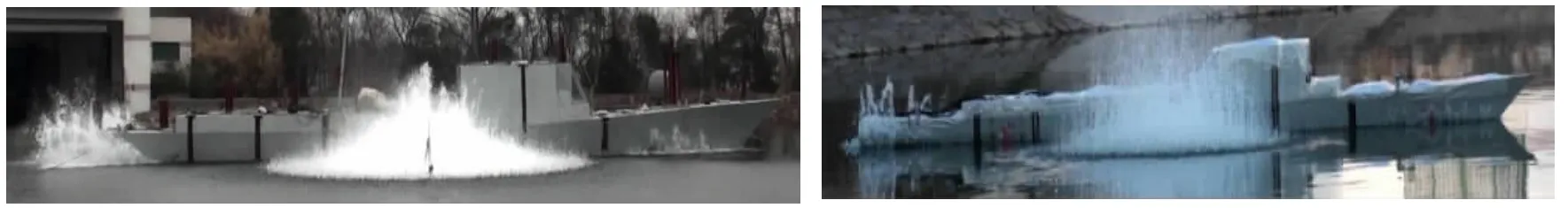
Fig.5 Test scene of the prototype and model to underwater explosion in CSSRC
3 Experimental results
3.1 Experiment cases
Experiment cases are designed in different keel shock factors SFkldefined by(1+sinα)W0.5/2R,different attack angles α,various frequency ratios of the first vibration mode to the first pulsation of the bubble ξ,and different positions in longitude.Cases are then all experimented not in the simulated subspace but near the boundary.All experimental cases are listed in Tab.4 in detail.The experiment scheme is shown in Fig.6.In all cases,the charge weights are scaled bythe distances from the detonation charge to the keel of the model are strictly scaled by λl,thus the keel shock factors are scaled byIn cases 10 and 11,the detonation position of the subscale model experiment is not within the similar subspace,just keeping the charge weight W,the ratios ξ of the frequencies and the keel shock factor SFklsatisfy the scaling law introduced in Tab.1.From case 12 to case 16,the SFklare close and the ξ values become large.Strains of each cylinder are measured by strain gauges which are affixed to upside and downside of the cylinder,which are converted to the bending moment and deflection by test calibration.The disposing diagram of strain is also shown in Fig.6.
Tab.4 The experiment cases
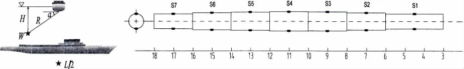
Fig.6 The schematic diagram of experiment case and strain gauges disposing
3.2 Results of subscale model
The deflection measure results at S4 position of subscale model in different cases with the same ξ=0.961 and different SFklare shown in Fig.7.The deflection is defined of vertical distance from any position of beam model to the straight line connected bow to stern.Fig.8 shows the responses are linearly increased by the keel shock factors,and the relation between maximal deflection ymaxand SFklis obtained:

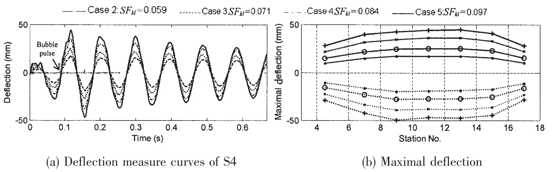
Fig.7 Comparisons of measure deflection in different cases
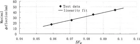
Fig.8 The relation between maximal deflection and SFkl
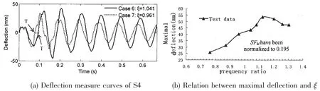
Fig.9 Comparisons of measure results in same SFkland different ξ
The measured results of subscale model are shown in Fig.9 of different cases that are all normalized to SFkl=0.195 of different frequency ratio ξ.From Fig.9(a),in the first period of the bubble pulsation,t<T,two deflection curves are consistent well on the amplitude.In case of ξ=0.961,the maximal deflection is in the second period of the first vibration mode.However when ξ=1.04,the maximal deflection value is achieved half period of the first vibration mode later than in case of ξ=0.961.There is some phase difference between the two load cases.Even if the test model is the same,the responses by bubble are delayed by the bubble pulsations when ξ becomes greater.Fig.9(b)also shows the maximal response increases with ξ increasing when its value is less than 1.124,and the maximal response decreases when its value is more than 1.124,and the whipping response reaches the maximal value when ξ=1.124.
Fig.10 shows the measured deflections at S2 position in different test cases that are in the same keel shock factor SFkl,ξ and γ.It shows the maximal response appears in the middle section when charge is located at L/2,while the maximal response appears in the L/4 or 3L/4 section when charge is located at L/4.It shows the component of 2nd mode whipping responses becomes larger when charge is at L/4,but the maximal responses with charge at L/2 are always about 2 times larger than charge at L/4 position.

Fig.10 Comparisons of deflection with different charge longitudinal position
Fig.11 shows the measured deflections at S4 strain gauge in different test cases that are just in the same keel shock factor SFkl=0.179 and ξ=0.961.The differences of the maximal whipping responses among each case are within 10%when both SFkland ξ are the same.
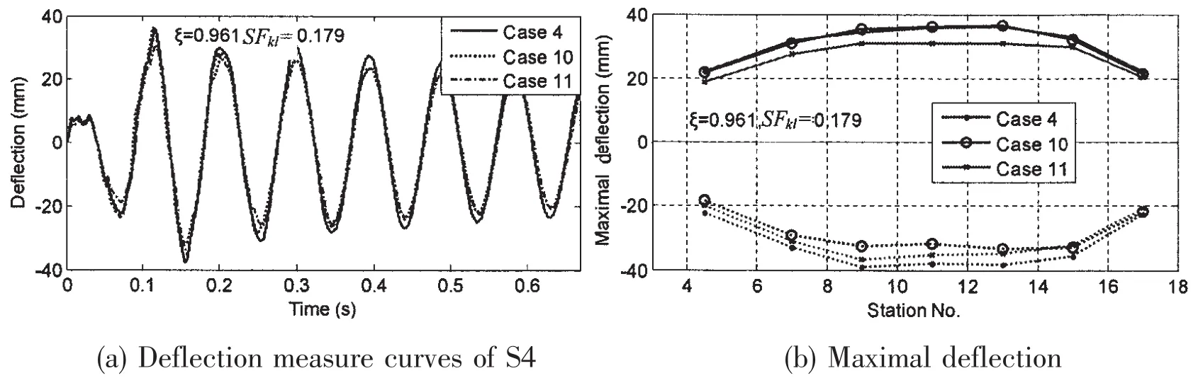
Fig.11 Comparisons of the measured results in same SFkland same ξ
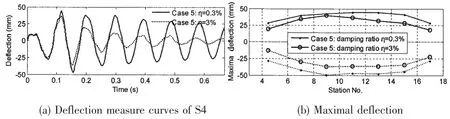
Fig.12 Comparisons of the deflection response with different critical damping ratios
It is found that the damping can seriously affect the maximal whipping responses.Fig.12 shows the comparison of the responses with different critical damping ratios.When the damp-ing ratio increases 10 times,the maximum responses will decrease about 20%.We also found that the damping varies with the amplitude of response.Fig.13 shows the damping ratio change along with time in case 7.The damping ratio decreases from 1.3%to 0.3%with the strain from 500 με to 50 με.The characteristics of damping may introduce difficulty to whipping response prediction and simulation.So it is worthy of further study.
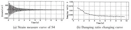
Fig.13 Curve of damping ratio changed along with strain response of subscale model
3.3 Comparing with results of prototype
Fig.14 to Fig.16 show the comparisons of moment measure results between prototype and 0.3 scale model.The test results of 0.3 scale model are converted by the scale law in Tab.1.It shows that the responses are consistent well between the prototype and the subscale model.
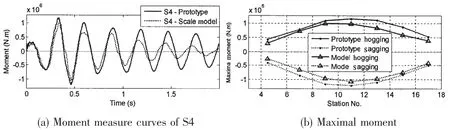
Fig.14 Comparisons of moment measure curves in case 2 with η=3%subscale model
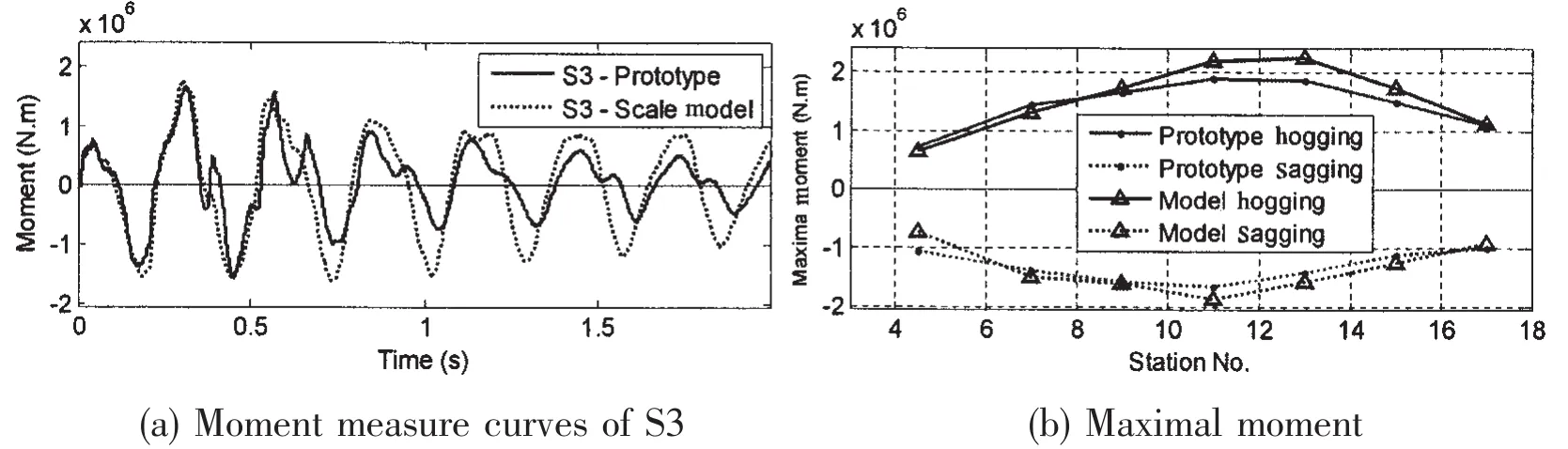
Fig.15 Comparisons of moment measure curves in case 7 with η=0.3%subscale model
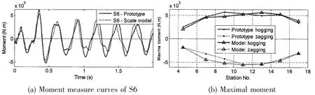
Fig.16 Comparisons of moment measure curves in case 8 with η=0.3%subscale model
Fig.17 shows the comparisons of test results between prototype and 0.3 subscale model in case 10 in which the detonation condition of subscale model is not in the similar subspace of LIS scale law,just keeping the charge weight W,the ratios of the frequencies ξ and the keel shock factor SFklsatisfy the scaling law.The comparisons results show that the simulation precise is still accepted.

Fig.17 Comparisons of moment measure curves in case 10 with η=0.3%subscale model
4 Conclusions
Two model tests are executed by applying the LIS scaling method to investigate the whipping responses of a surface ship to underwater explosions.Some relations between the whipping responses and the explosion parameters are investigated.The predicted responses by subscale model test are compared with those of the prototype and a good consistence is achieved.And an upward displacement compensating method is proposed for decreasing the bias from the subscale model test.Some meaningful results are achieved as follows:
(1)The most important parameters to the whipping responses are the keel shock factor and the ratio of the frequency of the first beam vibration mode to the first bubble pulsation,ξ.The maximum response was obtained with a similar keel shock factor when ξ=1.12.
(2)The whipping response increases linearly with the SFkl.
(3)Damping has obvious effects on the whipping responses.The critical damping ratios are relevant to the amplitude of the responses,and it decreases to the measurement value obtained from vibration test as the response decreases to small amplitude.
(4)The LIS scaling method has a good precise in modeling the responses of surface ship to underwater explosion.
Acknowledgements
Authors would like to thank He Bin,Yang Yunchuan,Cai Rongkun,Chen Hui,Zhang Keming,Mao Haibin and all colleagues in the explosion and shock division of China Ship Scientific Research Center for their high quality work on designing models,executing underwater experiments and measuring the responses.We also thank Dr.Wang Weibo for his advices on the paper.
[1]Chertock G.Transient flexural vibrations of ship-like structures exposed to underwater explosions[J].J Acoust.Soc.Am.,1970,48(1):170-180.
[2]Ma J,Zhang Q.The estimation of dynamic bending moment for a ship subjected to underwater noncontact explosions[C]//Proc.Int.Symp.On Mine Warfare Vessels and Systems.Rina,London,1984.
[3]Hicks A N.Explosion induced hull whipping[M].Advances in Marine Structures,edited by Smith C S,Clark J D,Elsevier Applied Science Publishers,1986:390-410.
[4]Li Y J,Pan J Q,Li G H,Zhang X C.Experimental study of ship whipping by underwater explosive bubble[J].Journal of Ship Mechanics,2001,5(6):75-83.
[5]Lua J,Godino V,Littlewood T,Miller R,Martini K.Dynamic response analysis of scaled steel hulls under direct shock wave and bubble loadings[C]//Proc.of 68th Shock&Vibration Symp.Hunt Valley,Maryland,1997:643-651.
[6]Schmidt R M,Voss M E,Housen K R,Holsapple K A.Subscale experiments to measure shock and bubble loading on responding structures[M].ASME Publication PVP-Vol.272,Sloshing,Fluid-structure Interaction and Structural Response Due to Shock and Impact Loads,1994:175-182.
[7]Liu J H,Wu Y S,Pan J Q,Wang H K.The scaling method for the whipping responses of a ship structure to underwater explosion[M]//Proceedings of Sixth International Conference of Navy and Shipbuilding Nowadays.St.Peterburg,Russia,June 30-July 1,2011,Section B-11,2011.
[8]Cole R H.Underwater explosion[M].Princeton University Press,1948.
- 船舶力學(xué)的其它文章
- Acoustic Radiation of Cylindrical Shells Submerged in the Fluid in Presence of the Seabed or Dock
- Influence of Thrust Bearing Pedestal Form on Vibration and Radiated Noise of Submarine
- Three-Dimensional Sono-elasticity Analysis of Floating Bodies
- Comparative Analysis of Some Fatigue Crack Propagation Models
- Development of Experimental Rig for Marine Propulsion Shafting and Longitudinal Vibration Characteristic Test
- Research on Multiple Excitations Inversion-oscillations