
Acoustic Radiation of Cylindrical Shells Submerged in the Fluid in Presence of the Seabed or Dock
2013-12-13 09:14:32YEWenbingLITianyunZHUXiangCHENChen
船舶力學(xué) 2013年3期
YE Wen-bing,LI Tian-yun,ZHU Xiang,CHEN Chen
(Department of Naval Architecture and Ocean Engineering,Huazhong University of Science and Technology,Wuhan 430074,China)
1 Introduction
The cylindrical shell is a typical element in the industrial fields.A significant amount of efforts has been dedicated to the study of the sound and vibration of submerged cylindrical shell[1-4].These researchers mainly focus on different types of cylindrical shells such as the shell with stiffeners and the shell with composite materials.In these papers,the fluid region surrounding the shells is assumed to be infinite and the sound field is considered as free space which means only traveling waves exist and the sound pressure can be expressed conveniently.
In practice,when the submarine runs near the seabed or the submarine is tested in the presence of dock,the fluid domain can be seen as semi-infinite and the seabed and the dock can be processed as rigid wall[5-6].The characteristics of the acoustic and vibration of the structure in this kind of fluid domain are much different from those in infinite fluid domain.Thus,it is very important to study the characteristics of the structure located in the semi-infinite fluid domain with the boundary of rigid wall which can help us predict the acoustic radiation of the structure quickly and exactly in the case.
For the fluid domain with the boundary of rigid wall,it is difficult to obtain the expression of the sound pressure.In some cases which include the boundary of free edge,the image method is usually used to deal with the boundary condition,which is a typical approach used in many fields such as electromagnetics,optics,acoustics,and so on.In order to impose an appropriate boundary condition on the free surface,Ergin[7]introduced a boundary integral equation method and the image method to study the free vibration of a partially liquid-filled and submerged,horizontal cylindrical shell.Hayir et al[8]presented a partially analytical study for the plate having a circular cavity subject to SH waves and proposed the image method to satisfy the boundary condition of the traction free surfaces on the plate.The dynamic stress concentration factors are analyzed in the paper.Li et al[9]studied the diffraction of sound by an impedance sphere in the vicinity of a ground surface and applied the image method to account for the effect of the ground surface.Hasheminejad et al[10]analyzed the modal vibrations of a cylindrical radiator over an impedance plane which consists of the boundary condition and the image method is adopted to solve the problem.Fang et al[11]investigated the multiple scattering of flexural waves and dynamic stress concentration from a cylindrical inclusion in a semi-infinite thin plate by using the image method to satisfy the boundary condition on the plate edge.
By adopting the image method,the boundary condition of the rigid wall is satisfied in this paper.The structure-fluid coupling vibration equations are established and the far-field sound pressure radiating from the submerged cylindrical shell in presence of rigid wall is analyzed by employing the stationary phase method[12].
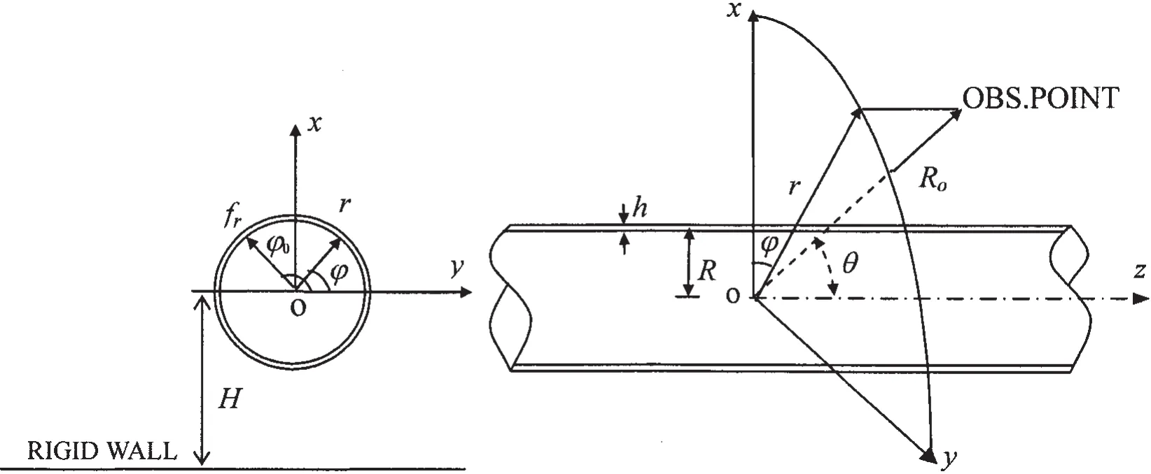
Fig.1 A submerged cylindrical shell and the corresponding coordinate system
2 Theoretical analysis
As in Fig.1,an infinite thin cylindrical shell of thickness h,mean radius R,Young’s modulus E,Poisson’s ratio μ,density ρs,is considered to be submerged in a fluid of density ρfwhere the velocity of sound is cf.The fluid domain is assumed to be semi-infinite.The cylindrical coordinates system(r,φ,z)is applied in this paper to define the position of points in the region above the rigid wall.The distance between the rigid wall and the center line of the cylindrical shell is denoted by H(H>R)and the cylindrical shell is excited by a harmonic point force frat the angle φ0.The observation point,which is defined in a spherical coordinates system,is introduced to define the position in the far-field which is located at a distance Ro,a polar angle of θ from the center line of the shell.
2.1 The motion equations of the shell
The Flügge shell equations are used to describe the motions of the cylindrical shell(For brevity,the factor e-iωtis omitted in the following expressions).

where[L]denotes the classical Flügge differential operator for thin shell theory:
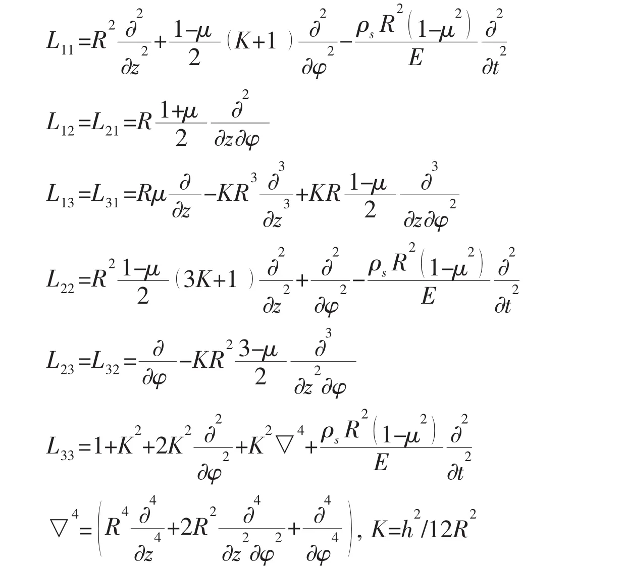
where u,v and w are the displacements of the shell in the z-,φ-and r-axes respectively.f0represents the load imposed by the fluid sound pressure on the surface of the cylindrical shell.
According to the wave propagation approach,u,v,w and f0can be expanded into Fourier series as follows[2]:
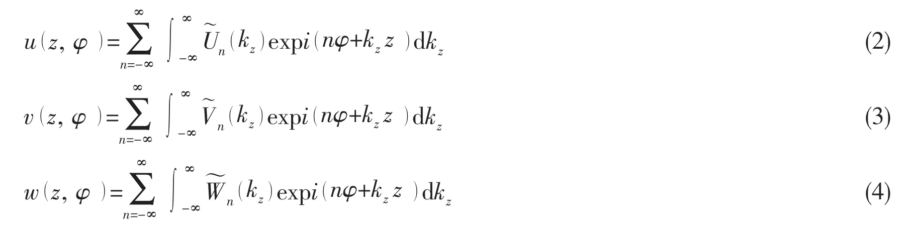

where n denotes the expansion coefficient,are the shell spectral displacement amplitudes in the z-,φ-and r-axes respectively,is the spectral load amplitude of f0and kzis the wave number in axial direction.
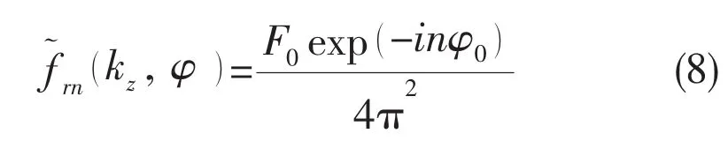
The point force can be expressed as:

where δ(·)denotes the Delta function.
By substituting Eqs.(2)-(6)into Eq.(1)and taking the Fourier transform and the orthogonal processing,the following equations are obtained:
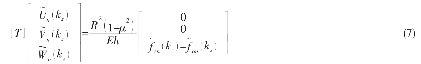
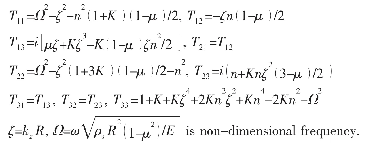
where the elements of matrix[T]are
2.2 Acoustic pressure expression
As it is shown in Fig.2,the cylindrical shell is located above the rigid wall.According to the image method[10],the sound radiation field is superimposed by the part that is directly radiated from the real source and the other part that is reflected by the rigid wall.The reflection part can be seen as that is radiated directly from a mirror image source of the real source in respect to rigid wall.And the acoustic pressure of any point A in the fluid field can be expressed as follows:
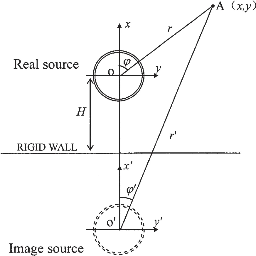
Fig.2 The sketch of the image method

where pr(r,φ,z)is the sound pressure radiated from the real source and pi(r′,φ′,z)from the image source.
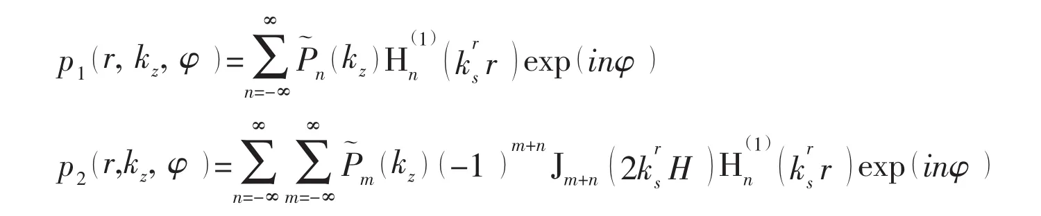
The two parts also satisfy the Helmholtz equation,and then they can be expressed as follows:
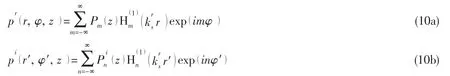
where m is the expansion coefficient,is the nth order Hankel function of the first kind,are the pressure amplitude,
Considering the normal velocity on the rigid wall is zero,the following relationship can be obtained at certain point(Rs,φs)on the rigid wall:
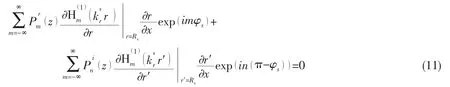
From Fig.2,the following relations can be expressed as:

By applying the derivation processing,the following equations can be obtained:

When the point A is located on the rigid wall with x=-H,the relation can be expressed as:

By taking the orthogonal processing and using the identityand Eq.(14),the following equation is obtained:

By substituting the Eqs.(10),(15)into Eq.(9),the following expression is obtained:

According to the Graf’s addition theorem for the Bessel functions,the second term of the right part in above equation can be expressed as follows[12]:
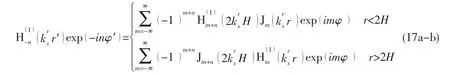
where Jm(·)is the mth order Bessel function.
2.3 The structure-acoustic coupling equation
By combining the Eqs.(17a)and(16),the sound pressure of the fluid field near the surface of the cylindrical shell(r<2H)is expressed as:
Then the load on the surface of the cylindrical shell imposed by the sound pressure in wave-number domain is obtained:

Considering the boundary condition at the interface between the cylindrical shell and the fluid,the following equation is obtained:

By introducing the Eqs.(4),(18)into Eq.(20)and taking the Fourier transform,can be represented as:
By combining the Eqs.(7),(8),(19)and Eq.(21),the structure-acoustic coupling equation can be expressed as:


where
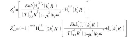
where[T]-1denotes the inverse matrix of[T].
2.4 Far-field sound pressure
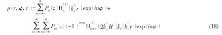
It is assumed that the far-filed is confined to the domain r>2H.By substituting the Eqs.(17b)into Eq.(16),the following equation is obtained:

where
By introducing the inverse Fourier Transform to the Eq.(23),then:

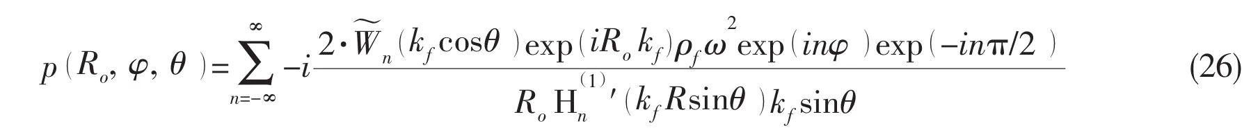
After applying the stationary phase method[2]and transforming cylindrical coordinates in above equation to spherical coordinates by the identity r=Rosinθ and z=Rocosθ,the far-field sound pressure radiating from a submerged cylindrical shell at a finite distance from the rigid wall can be expressed as:

According to the Ref.[2],the far-field sound pressure radiating from a cylindrical shell submerged in infinite fluid is expressed as:
Finally,the following expression is introduced to calculate the sound pressure level(SPL)in far-field:

where p0=1×10⁻⁶Pa.
3 Numerical results and discussion
The following parameters of the coupling system have been used in the calculations.The material of the cylindrical shell is assumed to be steel:E=2.1×10¹¹Pa,μ=0.3,ρs=7 850 kg/m3,and h=0.05 m and R=1.0 m.The surrounding fluid is considered to be water:cf=1 500 m/s and ρf=1 000 kg/m3.The amplitude and circumferential angle of the radial harmonic point force are supposed to be F0=1N and φ0=0.The polar angle of the observation point is assumed to be θ=π/2 in all following results.To avoid possible confusion,it is necessary to make clear that the far-field observation points in following results are located in the domain above the y-z plane as depicted in Fig.1.
Considering that the fluid domain can be processed as the infinite field when the distance from the rigid wall is large enough[5].The circumferential distribution of sound pressure(-π/2≤φ≤π/2)at the typical frequencies Ω=0.3,1.2 and 3.0[13-14]when the distance H=100 m,300 m and 600 m is investigated and compared with those when the fluid domain is considered to be infinite.The distance of the observation point is assumed to be Ro=1 500 m for satisfying the condition r>2H.The results are shown in Fig.3.It is found that the distribution of the far-field sound pressure radiated from the submerged cylindrical shell at a finite distance from the rigid wall shows differences with those from the cylindrical shell in infinite field.With the increasing of the distance,the far-field sound pressures in semi-infinite domain tend to agree with those in infinite fluid at a certain frequency.
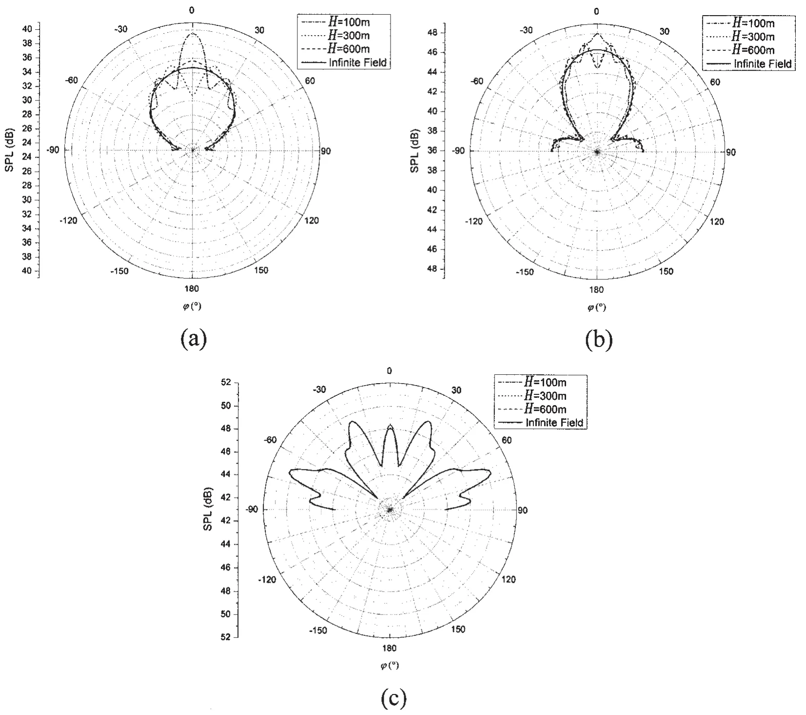
Fig.3 Comparison of the far-filed pressure in semi-infinite and infinite fluid(a)Ω=0.3;(b)Ω=1.2;(c)Ω=3.0
From the Fig.3,it can also be found that when increasing the excitation frequency and decreasing the distance H,the far-field sound pressure in our work agrees well with the infinite field.In order to describe the relation clearly,the following equation is introduced to evaluate the gap of far-field sound pressures between in the cases of our work and infinite field:

where Psemi-finitedenotes far-field sound pressure level at certain observation point when the cylindrical shell is immersed at a finite distance from the rigid wall,and Pinfinitecorresponds to that in infinite field.
The gap is investigated at the observation point(in this case Ro=600 m,φ=π/8,θ=π/2)and the results is shown in Fig.4.It is clear that the gap becomes small with the increase of the distance H.The error curves drop more quickly while the excitation frequency is higher.
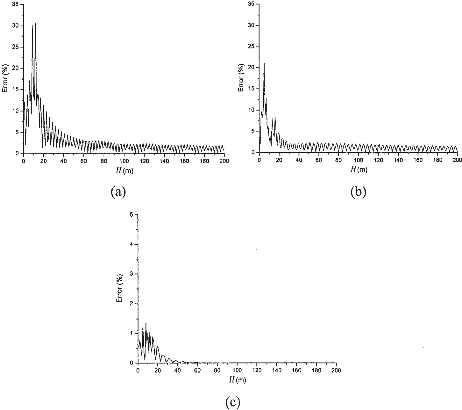
Fig.4 The error varying with the distance:(a)Ω=0.3;(b)Ω=1.2;(c)Ω=3.0
Fig.5 shows the circumferential distribution of far-field sound pressure when the cylindrical shell is located at a relatively small distance from the rigid wall at the frequency Ω=0.3,1.2 and 3.0 respectively.The distance of the observation point is assumed to be Ro=50 m in this case.It can be seen that the directivity of the far-field sound pressure varies with the distance H and the petal number is larger when the frequency is higher.
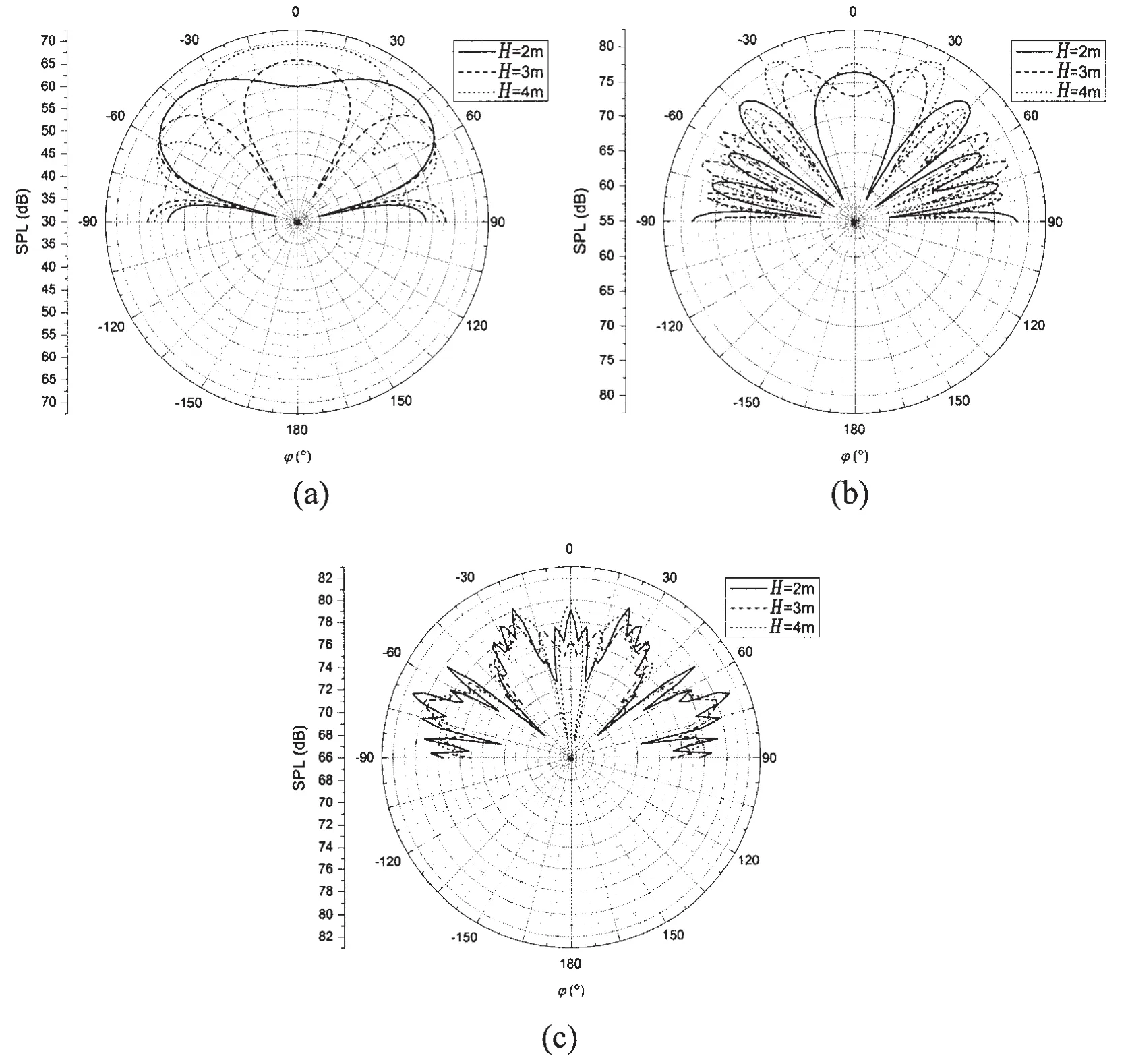
Fig.5 The far-field sound pressure radiated from the submerged cylindrical shell with different distances from rigid wall:(a)Ω=0.3;(b)Ω=1.2;(c)Ω=3.0
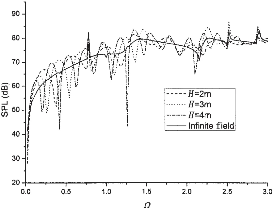
Fig.6 The far-field sound pressures varying with frequencies at a certain observation point
Fig.6 illustrates the far-field sound pressure varying with frequencies when the distance H=2 m,3 m and 4 m at the observation point(Ro=50 m,θ=π/2,φ=π/8).It is found that the far-field sound pressure fluctuates with the frequency in the low and high band in the case of finite distance due to the superposition of the direct waves and the reflected waves from the rigid wall,while the sound pressure varies smoothly in the infinite field.
The far-field sound pressure varies with the distance H at the observation point(Ro=50 m,θ=π/2,φ=π/8)when the frequency Ω=0.3,1.2 and 3.0 is given in Fig.7.It is clear that the sound pressure fluctuates with the distance H at all frequencies and this fluctuation is larger as the frequency increases.As shown in Fig.7,the distance of the adjacent peak points is as-sumed to be d and the wavelength of the wave which propagates in the fluid is denoted as λ.The ratio of the distance to the wavelength at different frequencies is shown in Tab.1.It can be found that the ratio at different frequencies tends to be the same value 0.5 which means that when the change of distance H is a multiple of 0.5λ,the peak or valley point appears.
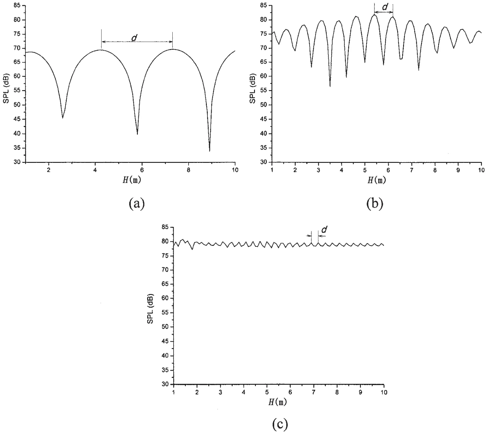
Fig.7 The far-field sound pressure varying with the distance H at certain observation point:(a)Ω=0.3;(b)Ω=1.2;(c)Ω=3.0
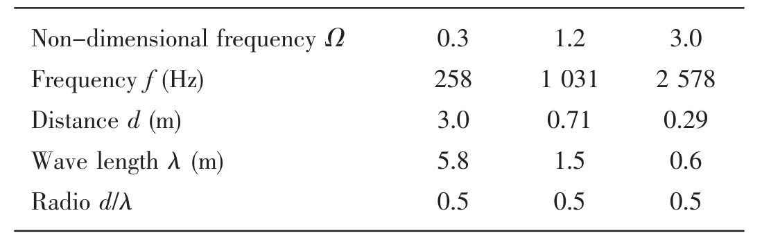
Tab.1 The radio of the distance d and the wave length λ at different frequency
In the presence of the rigid wall which can reflect the waves,the sound pressure at a certain point consists of two parts.One part is the sound pressure radiated by the cylindrical shell directly and the other part is the sound pressure reflected by rigid wall.The superposition of these two parts either enhances or weakens the sound pressure at a certain point which results in the fluctuations in above curves.At low frequencies,the wavelength is relatively large and the oscillations of the sound pressure with the depth are relatively slow.With the increase of the frequencies,the wavelength becomes more and more small and the pressure fluctuates with the depth more quickly which can be found from above results.
4 Conclusions
By adopting the image method and the stationary phase theory,the characteristics of the far-field sound pressure radiating from a submerged cylindrical shell at a finite distance from the seabed or dock are obtained and the results are compared to those from the cylindrical shell in infinite fluid.It is concluded that the results of two cases are different due to the presence of seabed or dock.The distribution of the far-filed sound pressure in the two cases becomes very close when the distance is large enough.When the cylindrical shell is immersed at a small distance from the seabed or dock,the distribution shows obviously differences.The far-field pressure exhibits oscillation with the change of the distance and the extent of the oscillation is intensified with the increase of the frequency which is decided by the ratio of depth to wavelength.
Acknowledgements
The authors wish to express their gratitude to National Natural Science Foundation of China(Contract No.40976058)that has supported this work.
[1]Pathak A G,Stepanishen P R.Acoustic harmonic radiation from fluid-loaded infinite cylindrical elastic shells using elasticity theory[J].The Journal of the Acoustical Society of America,1994,96(1):573-582.
[2]Junger M C.Sound,structure and their interaction[M].Cambridge:M.I.T.Press,1979.
[3]Burroughs C B.Acoustics radiation from fluid-loaded infinite circular cylinders with doubly periodic ring supports[J].Journal of the Acoustic Society of America,1984,75(3):715-722.
[4]Guo Y P.Acoustic scattering from cylindrical shells with deck-type internal plate at oblique incidence[J].Journal of the Acoustic Society of America,1994,96(1):287-293.
[5]Zou Y J,Zhao D Y,Li S.Impact of soft surface and hard plane on structural vibration and acoustic radiation[J].Acta A-custica,2005,30(1):89-96.
[6]Cao W W,Chen M,Guan S S,The discussion of the calculation of the acoustic radiation from the structure in presence of dock[C]//Proceeding of 12th Underwater Noise of Shipbuilding.Changsha,2009.(in Chinese)
[7]Ergin A.Free vibration of a partially liquid-filled and submerged,horizontal cylindrical shell[J].Journal of Sound and Vibration,2002,254(5):951-965.
[8]Hayir A,Bakirtas I.A note on a plate having a circular cavity excited by plane harmonic SH waves[J].Journal of Sound and Vibration,2004,271(1-2):241-255.
[9]Li K M,Lui W K.Frommer G H.The diffraction of sound by an impedance sphere in the vicinity of a ground surface[J].Journal of the Acoustic Society of America,2004,115(1):42-56.
[10]Hasheminejad S M,Azarpeyvand M.Modal vibration of a cylindrical radiator over an impedance plane[J].Journal of Sound and Vibration,2004,278(3):461-477.
[11]Fang X Q,Wang X H.Multiple scattering of flexural waves from a cylindrical inclusion in a semi-infinite thin plate[J].Journal of Sound and Vibration,2009,320(4-5):878-892.
[12]Lee W M,Chen J T.Scattering of flexural wave in a thin plate with multiple circular holes by using the multipole Trefftz method[J].International Journal of Solids and Structures,2010,47(9):1118-1129.
[13]Xu M B,Zhang W H.Vibrational power flow input and transmission of a circular cylindrical shell filled with fluid[J].Journal of Sound and Vibration,2000,234(3):387-403.
[14]Yan J,Li F C,Li T Y.Vibrational power flow analysis of a submerged viscoelastic cylindrical shell with wave propagation approach[J].Journal of Sound and Vibration,2007,303(1-2):264-276.
- 船舶力學(xué)的其它文章
- Influence of Thrust Bearing Pedestal Form on Vibration and Radiated Noise of Submarine
- Three-Dimensional Sono-elasticity Analysis of Floating Bodies
- Comparative Analysis of Some Fatigue Crack Propagation Models
- Development of Experimental Rig for Marine Propulsion Shafting and Longitudinal Vibration Characteristic Test
- Research on Multiple Excitations Inversion-oscillations
- Application of the Loading Inherent Subspace Scaling Method on the Whipping Responses Test of a Surface Ship to Underwater Explosions