
Characteristics of Tendon Vortex Induced Vibrations Influenced by Platform Motion
2015-12-12 08:52:14GUJiayangYANGJianmin
船舶力學 2015年6期
GU Jia-yang,YANG Jian-min
(1 School of Naval Architecture and Marine Engineering,Jiangsu University of Science and Technology,Zhenjiang 212003,China;2 State Key Laboratory of Ocean Engineering,Shanghai Jiao Tong University,Shanghai 200240,China)
0 Introduction
A tendon system is composed of multiple sets of tight steel cables,and the quantity of steel cables is related to the shape of the superstructure of the platform.Each cable group comprises a number of steel cables or steel bar bundles,and the bottom of each cable group is fixed directly in the anchor foundation to generate tension and balance the extra buoyancy of the platform.The tendon system not only controls the relative positions between the platform and the wellhead but also plays a crucial role in security.At a certain incoming flow velocity,the alternate shedding vortexes behind both sides of the tendon are observed.These alternating shedding vortexes significantly influence the dynamic response of the tendon and show various modal characteristics.
The tendon of the tension-leg platform(TLP)and the riser have similar dynamic characteristics,but the geometry size and pre-tension of the tendon are larger than the riser.Nevertheless,related research on the vortex-induced vibrations(VIVs)of deep-sea risers provides references on tendons.To date,the main prediction methods for marine riser VIVs are experimental investigation and numerical simulation.Experimental investigation is reliable but involves considerable human,material,and financial costs.Experimental investigation can be divided into field measurement and scale rule research,which is performed in the laboratory.The numerical simulation of riser VIV involves the classical wake oscillator model and computational fluid dynamics(CFD).
Studies on the VIVs of tendons have relied mainly on theoretical research.Dong Yanqiu[1]from Tianjin University studied tendon VIVs at a certain incoming flow velocity.Chen Wei[2]performed numerical simulations on a riser VIV of ocean engineering by using strip theory.Willden and Graham[3]created a CFD model based on strip theory to obtain the numerical simulation of riser VIV in uniform flow.Schulz and Meling[4]used strip theory with the Reynolds averaged Navier-Stokes(N-S)equation and finite element method to analyze the fluid-structure interaction of risers.Huang Zhiyong[5]created a riser VIV prediction model and used strip theory with the turbulence model to obtain the interaction between the riser and fluid.Chaplin et al[6]studied the physical model of riser VIV and analyzed the modal response,amplitude,and frequency of the riser.
Huera-Huarte and Bearman[7]studied the VIV of vertical,slender,and flexible risers.They found that the riser exhibited a low modal response and that the first order mode played a vital role.The riser employed in their experiment had a mass ratio of 1.8 and an m*ξ of 0.05.The influence of different pre-tension values in riser VIV was considered,and the pre-tension ranged from 15 N to 110 N.McSherry[8]performed an experimental study and numerical comparison for marine riser.The mass ratio of the riser was close to 1 400 and was located in the subcritical region.A numerical simulation of the riser fluid-structure interaction was performed by using strip theory,and the triple and quintuple principal oscillation frequency resonances of the transverse direction were simulated.Double and triple principal oscillation frequency resonances at the flow direction were also simulated.
Lima et al[9]researched marine riser VIV dynamic response and fatigue characteristics by numerical simulation.DVM was employed to calculate the fluid forces on each riser profile along the axis direction.Soni and Larsen[10]calculated the riser VIV by using strip theory and discussed the computational accuracy.They first recorded the track of some profiles by using a riser VIV experiment and then made a rigid cylinder move on the same track to measure the relevant hydrodynamic load.The measured loads of each profile were applied to the riser by using the finite element method and were compared with the experimental results.Aronsen[11]discussed the calculations of the flexible beam and locus diagram of the rigid column model.The results confirmed that strip theory is feasible and that the assumptions are correct.Yamamoto et al[12]used the method based on strip theory to study the VIV of a slender column.Fluid forces on a 2D slice were calculated by using DVM.The coupled solution of the structure dynamic response of each slice was solved by using a 3D finite element method.
He Changjiang et al[13]employed strip theory with the finite element and finite volume methods to conduct the numerical simulation of the vortex-induced motions(VIMs)of a slender,flexible riser.The scale ratio of the riser was 250,and the mass ratio was 2.9.The calculation results show that the flow direction and transverse motions are coupled because they both change with decreasing velocity.Lie and Kaasen[14]performed a modal analysis of riser VIV in shear flow by experimentation.The experimental results suggest that the response of the riser presents irregularity,i.e.,the response of the riser became more irregular with increasing velocity.In their study,a single modal response is not discovered.Srinil et al[15]used the order reduction method with the fluid-structure coupled model to study riser VIV under the flow effect.The riser model had simple supported beams,and the wake oscillator model improved by Skop and Balasubramanian[16]was employed to solve the flow force changes with time and space.Srinil et al[17]also studied the multi-modal response of a marine riser in uniform flow and shear flow.A reduced-order model was used in a numerical simulation to predict the response of the riser VIV and to compare such response with the experimental results.
Srinil[18]studied the VIV of variational tension riser in shear flow.The model was based on a simply supported and varied tension beam.The nonlinear wake oscillator model based on the diffusion term of the experimental data was employed to simulate the riser lift.Huang et al[19]studied the VIV of slender riser in shear flow using a three-dimensional overlap grid and a Reynolds averaged N-S method.Constantinides and Oakley[20]employed the CFD method to study the 3D VIV and scale ratio of a riser(L/D)over 4 000.A resonance phenomenon was observed by comparing the numerical simulation with the experimental data.Lie et al[21]proposed an entire 3D model to predict the fatigue damage of the riser caused by VIV.The responses of the flow direction and transverse motions and their random characteristics were studied.Nozawa et al[22]studied the aspect of energy conservation and improved LINE3D_VIV software by using a nonlinear finite element method based on a subaqueous linear structure to simulate the VIV of a deep-sea riser and perform fatigue prediction.
In ocean engineering,only the frequency forecast model is employed in the prediction of slender marine riser VIV(e.g.,mature business software VIVANA,SHEAR7,and Vieomo).By using frequency prediction,the following can be achieved:riser and tendon VIV prediction in the time domain,recording of flow field change with riser and tendon dynamic responses,analysis of the coupling between ocean engineering structures and flow field,discovery ofVIV mechanism,and mastery of VIV regulations and features.In current academic circles,the timedomain model employed for studying the dynamic characteristics of slender ocean structure VIV is based largely on direct numerical simulation,which depends on 3D models or numerical methods that depend on 2D strip theory.The simulation of 3D direct computation is reliable,accurate,and reflects the 3D effect of structures.However,this type of simulation is mainly used for relevant research at low Reynolds numbers.The 3D flow field based on strip theory is equivalent to several 2D flow fields and ignores the 3D correlation of the flow field to some extent.Nevertheless,the 3D flow field based on strip theory improves calculation efficiency and minimizes wastage of calculation resources.
2 Study on tendon VIV by using the nonlinear dynamical method
A tendon is composed of a steel tube.Pre-tension is applied in pre-installation to simplify the tendon into beam mode.The vibration equation of the tendon can be expressed as follows:

where EI is the bending rigidity of the tendon,T0is the pre-tension,ω is the exciting frequency of the parameter,T is the dynamic tension,C is the viscous damping coefficient of the structure,m is the mass per unit length of the structure,and Fyis the total fluid forces per unit length along the y direction.
The fluid forces on the tendon can be divided into two parts:the lift caused by the vortex train,and the fluid damping force caused by the transverse motion,

The formulas for the vortex train lift are as follows:
where ρLis the water density,D is the tendon diameter,Vcis the flow velocity,CLis the lift coefficient,wsis the shedding vortex frequency,and u is the horizontal wave speed.
The fluid forces on the tendon can be calculated by using Morison’s formula,which is appropriate for small-scale ocean structures:

Galerkin’s method is performed to expand the transverse displacement y(z,t)into a vibration mode series form:

By combining Eq.(6)with Eqs.(3)and(5)and then combining the resulting equation into Eq.(1),the following equation is derived:
According to Galerkin’s method,the following equation is derived:
By rearranging Eq.(8),we obtain the following:

ning term that can be calculated by using the following formula:

Based on Eq.(10),the following equation is derived:

2 Relevant parameters of the slice model and calculation process
The tendon is dispersed into 36 cells along the axis line.The section of each cell can be considered a corresponding 2D flow field(Fig.1).The calculation model of each slice is shown in Fig.2.The mesh size of all models is 40D×70D.The left side of the model is set as the velocity inlet boundary,the right side of the model is set as the outflow boundary,and the upper and lower boundaries of the model are set as symmetry.The origin of the coordinates is located in the center of the cylinder.The left boundary and center are 20D apart,the right boundary and center are 50D apart,and the lower boundary,upper boundary,and center are 20D apart.Dynamic mesh technology is used to update the flow field,and a movement zoom size of 6D is placed around the section of the tendon to move the circular cross section.This method can ensure grid quality during the movements.

Fig.1 Sketch of the numerical calculation model
Fig.2 (a)Partial slices of the numerical calculation model and(b)slice map of a single flow field
The vibrational response equation of the tendon can be discretely solved by using the fourth-order Runge-Kutta method.The Reynolds averaged N-S equations can be discretely solved by the finite volume method.Thus,the VIV of the tendon at a certain incoming flow in the time domain can be simulated by using a combination of the two aforementioned methods.The interface between these methods is accomplished by using the user-defined functions of Fluent.
Two loop programs are employed to implement iterations in the numerical simulation of tendon VIMs.The outer loop is used to complete the iterations of the time step,and the inner loop is used for the loop of the slices.A flow field solver is employed per time step to solve the N-S equation and obtain the flow field information to extract the fluid forces on each section of the tendon.The fluid forces are then assembled into an external load and combined with the structural dynamic equations to calculate the velocity and displacement of each section.The parameters of the flow field are finally updated.
The tendon is dispersed into 36 cells along the length direction.Each cell denotes L/36 length.The plane of each cell is regarded an independent flow field,and the first 7 order modes are considered.The fluid at a certain velocity flows through the tendon at time t.The fluid forces of 36 typical positions solved at time t in n-order mode are integrated into the tendon direction to obtain the n-order modal fluid forces of formula(9).The value of the right correlation parameters of the 7 order modal equations can also be solved in the same manner.The 7 second-order differential equations are processed by solving the simultaneous equations to obtain the value of the flow velocity and displacement in any section at time t+Δt.The displacements of the 36 nodes are then superimposed to obtain the displacement of the tendon along the length direction at time t+Δt.Thus,the deformation of the tendon can be confirmed at time t+Δt.The deformation at time t+Δt becomes the initial position of the next time value to calculate the succeeding fluid forces and confirm the deformation of the next time t.The displacement of the tendon at any moment can be solved by repeating the above steps to confirm the dynamic response characteristics.
3 Study on tendon VIV influenced by platform motion
Tendon tensions are assumed constant values in the study because the marine environment of the TLP influences such tensions.This hypothesis must exist in great idealization.The forces on the tendon are closely connected with the platform motion.The VIV characteristics must be influenced by the varied tensions of the tendon.The time-variant tensions of tendon VIV under the joint action of wave and current are then studied and compared with relevant conclusions in constant tension.
The VIV under the following typical working conditions are studied:(1)Flow velocity of 1 m/s and wave height of H3;(2)Flow velocity of 1 m/s and wave height of H5;(3)Flow velocity of 2 m/s and wave height of H3;(4)Flow velocity of 2 m/s and wave height of H5.
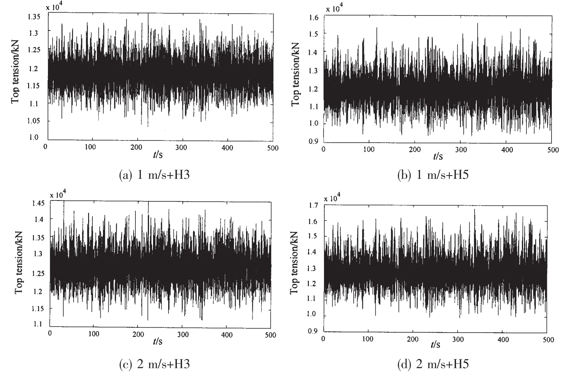
Fig.3 Time history curve of the tendon tensions in each condition
DNVDeepC software is used to calculate the tension of the mooring system and tendon under different sea conditions.The tendon tension at different times is extracted for the VIV calculation in the next step.The time step Δt=0.05 s and total 500 s are the costs.The time history curves of the tension in the four typical working conditions are shown in Fig.3.At the same flow velocity,the tension of the tendon in wave height H5 is greater than in H3.At the same wave height,the tension at flow velocity 2 m/s is greater than the tension at 1 m/s.
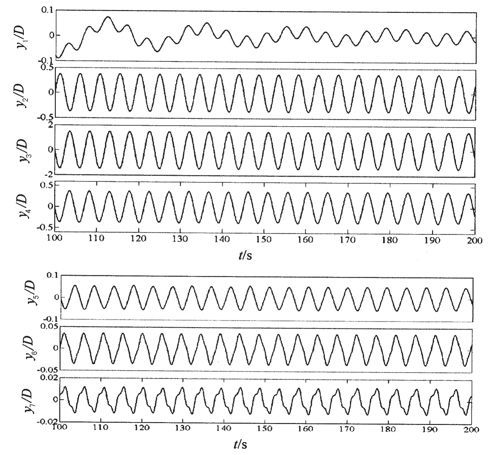
Fig.4 Tendon VIV transverse amplitude weight yi (1 m/s+H5)
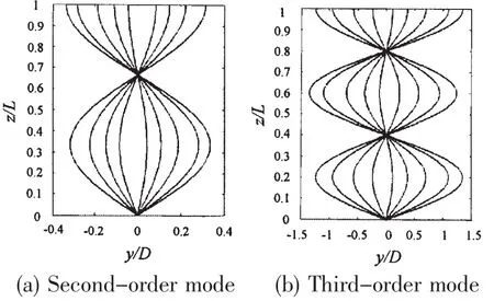
Fig.5 Response modes inspired by the tendon
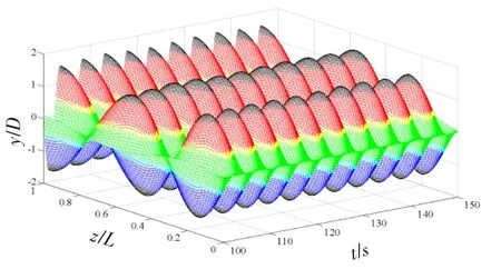
Fig.6 Time history response along the tendon direction
However,given the lack of space,the weight-time-history curves of each mode,the curves of the response mode inspired by the tendon,and the time history curves of the tendon at different heights are only shown at flow velocities of 1 and 2 m/s at a wave height of H5.Figs.4 to 6 show the relevant calculation results at flow velocity 1 m/s and wave height H5.Figs.7 to 9 are the relevant calculation results at flow velocity 2 m/s and wave height H5.
The second-and third-order modes inspired by the tendon at flow velocity U=1 m/s and wave height H5 are shown in Fig.5.The third-order mode plays the dominant role in the entire calculation period,closely followed by the second-and fourth-order modes(Fig.4).For the regularity of the weight map,the other five modes display satisfying regularity and periodicity,except for the first-and seventh-order modes.The essential differences between the calculated,experimental,and numerical simulation results of VIV are found in this study whether in steady or time-varying tension.In the riser VIV,the jump phenomenon may occur in the weight of each mode at different times.In the study on riser VIV,the fixed modal response of a riser is set to a stationary wave.This condition indicates that the waveform of the riser mode maintains a certain shape.The jump phenomenon between modes is called a‘traveling wave’,which is not found in literature on tendon VIV.The stationary wave is closely related to the boundary conditions of TLP VIV.The response curves of the tendon at different heights and times are shown in Fig.6.
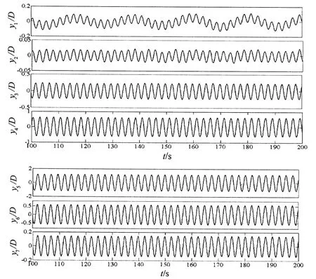
Fig.7 Tendon VIV transverse amplitude weight yi (2 m/s+H5)
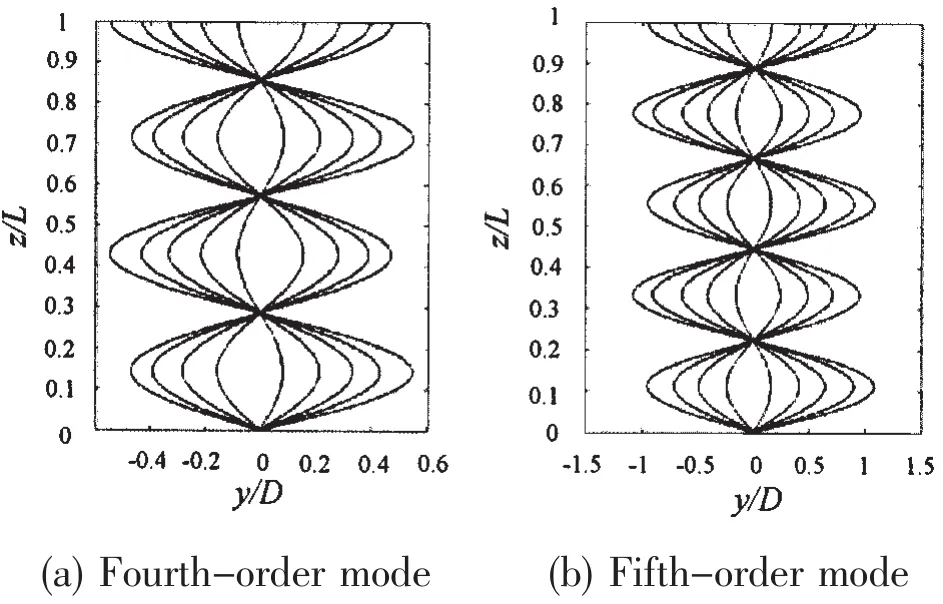
Fig.8 Response modes inspired by the tendon
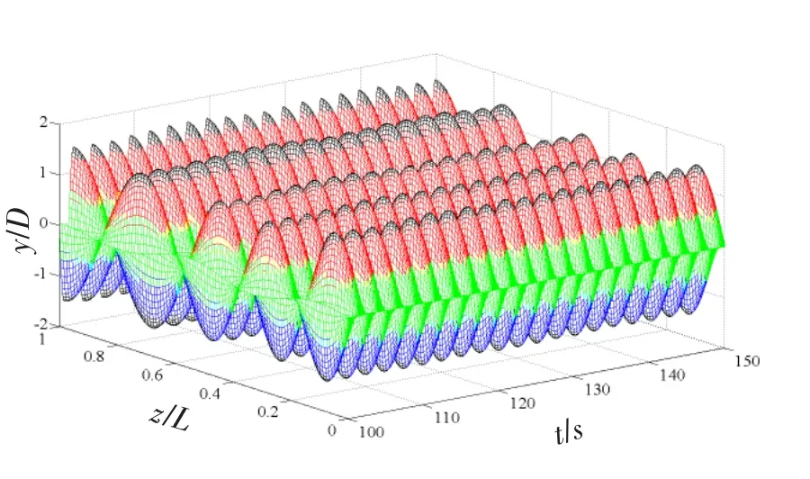
Fig.9 Time history response along the tendon direction
The dynamic response of each mode of tendon VIV under six working conditions,i.e.,four typical working conditions and two steady tension conditions,are provided in Tab.1.The results of the tendon time-varying tension influenced by platform motion are very close to the results of the steady tension influenced only by the current.At flow velocities of 1 m/s and 2 m/s,the results of the modes agree well with each other in wave heights H3 and H5 regardless of the weight response values of each mode or the occurred order of the dominant mode.The waves have insignificant influence on tendon VIV(Tab.1).The computation of the steady tension is compared with the computation of the time-varying tension.This comparison shows similar results.Some mechanical characteristics of the eight TLP tendons in the random wave are found.In a low sea state,the changing amplitude of the tendon tension is small and the average values of the tension forces on each tendon oscillate around the initial tension.In the present investigation of riser VIV,the tension is always set to equal the initial pre-tension.By combining the results of tendon VIV,we can conclude that tension fluctuations because of platform motion have limited effects on tendon VIV.
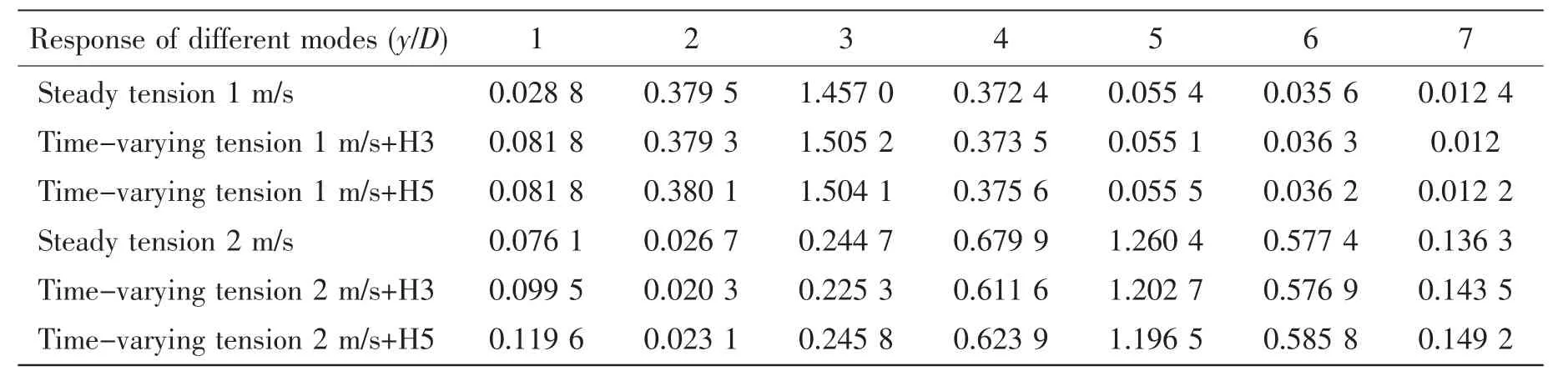
Tab.1 Dynamic response of each mode of tendon VIV in steady and time-varying tensions

Fig.10 Trailing vortex structures of each flow field slice along the tendon direction
The trailing vortex-structure release pattern of tendon VIV is similar to that of the elastic support columns.Each cell of the tendon can be considered a transverse vibration column.The trailing vortex structure of the elastic support columns provides guidance to the trailing vortex-structure pattern of the tendon.This paper shows the trailing vortex structures of the flow field located in z/L=0.08,z/L=0.33,and z/L=0.67 at the same shed vortex period in flow velocity 2 m/s and wave height H3.Each line represents a trailing vortex structure at a different location,whereas each column represents a trailing vortex structure at different moments(Fig.10).The trailing vortexes behave as 2P patterns at different times and different positions.These vortexes are different from the trailing vortex structure of the riser.Thus,a certain relationship between the mass ratio and the flow velocity exists.Although the trailing vortexes all behave as 2P patterns,the release methods and release positions are different.
4 Conclusions
In this paper,the influence of platform motion on tendon VIV is considered and the nonlinear equations of tendon VIV are established.By using CFD and the slice method,relevant UDF programs are created to calculate the tendon VIV in time-varying tensions.The fourthorder Runge-Kutta method is employed to solve the differential equations of structure motion,and the solver code is embedded to the UDF.The flow field is updated by dynamic mesh technology.DEFINE_CG_MOTION functions are used to extract fluid forces and transport such forces to structure equations to calculate transient motion responses.The conclusions are presented as follows:
(1)Tendon VIVs in steady tension are investigated by the slice method.The displacement influenced by the tendon at flow velocity U=1 m/s is located in the third-order mode even though the displacement at flow velocity U=2 m/s is in the fifth-order mode.The results match the results from the classical method.The jump phenomenon clearly emerges in the weight proportion relation of each mode with increasing flow velocity.
(2)Given the dynamic response of the platform in wave and current action,the forces on the tendon vary and the tendon tension oscillates around the initial pre-tension.Only the timevarying tension of the tendon affected by the current or wave and current action is studied in this paper.A total of six working conditions including two types of typical wave heights are studied.The calculation results show that the forces on the tendon become stochastic when affected by platform motion but the VIV of the tendon is less affected by platform motion.
(3)Added mass is simplified in the UDF program.In this study,the ordinary process of added-mass coefficient is first integrated along the axial direction and then divided equally.Hence,the average value of the added-mass coefficient along the riser axial direction is obtained.Huang Zhiyong[5]indicated that a simple average cannot signify the added-mass coefficient of a riser VIV because the change in added-mass coefficient along the axial direction cannot be reflected.Although a different inspired mode corresponds to a different added mass,the added mass must have a certain undulation in a multi-modal response.During the processing of the multi-modal response of the riser,a possible modal response inspired by the riser should be confirmed first.The contribution of the corresponding added-mass coefficient of each mode based on the relevant proportion of each modal weight is then considered.The method of the corresponding added-mass coefficients of the three dominant modes that have high weights should be used to calculate the final added-mass coefficient.
[1]Ma Chi,Dong Yanqiu,Hu Zhimin.TLP VIV nonlinearity vibration[J].Journal of Tianjin University,2000,33(6):701-706.
[2]Chen Wei.Numerical simulation discrete vortex of VIV[D].Dalian:Master Degree Dissertation of Dalian University of Technology,2009.
[3]Willden R H J,Graham J M R.Multi-modal Vortex-Induced Vibrations of a vertical riser pipe subjected to a uniform current profile[J].European Journal of Mechanics-B/Fluids,23:209-218.
[4]Schulz K W,Meling T S.Multi-Strip numerical analysis for flexible riser response[C].Proceedings of the 23th International Conference on Offshore Mechanics and Arctic Engineering.OMAE,2004:379-384.
[5]Huang Zhiyong.The analysis of time domain response of flexible riser VIV[D].Shanghai:Dissertations of Shanghai Jiaotong University,2008.
[6]Chaplin J R,Bearman P W,Huera Huarteb F J,Pattenden R J.Laboratory measurements of vortex-induced vibrations of a vertical tension riser in stepped current[J].Journal of Fluids and Structures,2005,21:3-24.
[7]Huera-Huarte F J,Bearman P W.Wake structures and vortex-induced vibrations of a long flexible cylinder-Part 1:Dynamic response[J].Journal of Fluids and Structures,2009,25:969-990.
[8]McSheery R J,Willden R H J,Graham J R.Numerical simulations of the flow past cross-flow oscillating circular cylinders and marine riser pipes[C].Proceedings of the 26th International Conference on Offshore Mechanics and Arctic Engineering.OMAE,2007-29265.
[9]Lima A A,Meneghini J R,Mourelle M.Numerical investigation of vortex-induced vibration of a marine SCR[C].Proc.of the 26th International Conference on Offshore Mechanics and Arctic Engineering.OMAE,2007-29269.
[10]Soni P K,Larsen C M.Investigating the relevance of strip-theory for pipelines subjected to vortex induced vibration[C].Proc.of the 27th International Conference on Offshore Mechanics and Arctic Engineering.OMAE,2008-57551.
[11]Aronsen K.An experimental investigation of in-line and combined in-line cross-flow Vortex Induced Vibration[D].Ph.D.thesis,Faculty of Marine echnology,NTNU,Trondheim,2007.
[12]Yamamoto C T,Meneghini F,et al.Numerical simulations of vortex-induced vibration on flexible cylinders[J].Journal of Fluids and Structures,2004,19:467-489.
[13]He Changjiang,Duan Zhongdong,Ou Jinping.Numberical simulation of vortex-induced vibrations on a flexible riser in uniform currents[C].Proceedings of the 29th International Conference on Offshore Mechanics and Arctic Engineering.OMAE,2010-20178.
[14]Lie H,Kaasen K E.Modal analysis of measurements from a large-scale VIV model test of a riser in linearly sheared flow[J].Journal of Fluids and Structures,2006,22:557-575.
[15]Srinil N,Wiercigroch M,O’Brien P,Younger R.Vortex-Induced Vibration of catenary riser:Reduced-order modeling and lock-in analysis using wake oscillator[C].Proceedings of the 28th International Conference on Offshore Mechanics and Arctic Engineering.OMAE,2009-79116.
[16]Skop R A,Balasubramanian S.A new twist on an old model for vortex-excited vibrations[J].Journal of Fluids and structure,1997,11:395-412.
[17]Srinil N,O’Brien P,Younger R,Wiercigroch M.Numerical and experimental comparisons of vortex-induced vibrations of marine risers in uniform/sheared currents[C].Proceedings of the 29th International Conference on Offshore Mechanics and Arctic Engineering[C].OMAE,2010-20192.
[18]Srinil N.Analysis and prediction of vortex-induced vibrations of variable-tension vertical risers in linearly sheared currents[J].Applied Ocean Research,2011,33:41-53.
[19]Huang K,Chen H C,Chen C R.Time-domain simulation of riser viv in sheared current[C].Proceedings of the 26th International Conference on Offshore Mechanics and Arctic Engineering.OMAE,2007-29363.
[20]Constantinides Y,Oakley O H.Numerical prediction of VIV and comparison with field experiments[C].Proceedins of the 27th International Conference on Offshore Mechanics and Arctic Engineering.OMAE,2008-57215.
[21]Lie H,Larsen C M,Kaasen K E.Frequency domain model for prediction of stochastic vortex induced vibrations for deep water risers[C].Proceedings of the 27th International Conference on Offshore Mechanics and Arctic Engineering.OMAE,2008-57556.
[22]Nozawa T,Suzuki H,Ohta M.Numerical prediction and suppression of VIV of deepwater riser[C].Proceedings of the 29th International Conference on Offshore Mechanics and Arctic Engineering.OMAE,2010-20135.

- 船舶力學的其它文章
- Jacket Effects on Heave,Roll and Pitch Motions of a New Floating Deep-draft Semisubmersible Concept
- Convergence Method for Hydrodynamic Force on Surface Structures with Oblique Boundaries
- Influence of Excitation Location on Sound Radiation of a Simple Duct Excited by Sound Source
- Two-dimensional Eulerian-Lagrangian Modeling of Shocks on an Electronic Package Embedded in a Projectile with Ultra-high Acceleration
- Load-Compression Relationship of Incompressible Circular Rubber Pad Bonded between Rigid Plates
- Mechanical Behavior of Flexible Jumper Installation in 3D Space