
Load-Compression Relationship of Incompressible Circular Rubber Pad Bonded between Rigid Plates
2015-12-12 08:52:18ZHENGYikanZHANGShilian
船舶力學(xué) 2015年6期
ZHENG Yi-kan,ZHANG Shi-lian
(School of Naval Architecture,Ocean and Civil Engineering,Shanghai Jiao Tong University,Shanghai 200240,China)
0 Introduction
Rubber blocks bonded between two rigid plates have numerous engineering applications in the construction and transport industries,providing load-bearing,shock-absorption and vibration isolation.The modern automobile may have as many as 600 elastomeric components[1].The rubber components are usually rectangular blocks or circular pads,with bonded metal plates on both the upper and lower surfaces.Tsai and Lee[2]indicated the restricted lateral expansion on the bonded surfaces of the elastic layer causes higher compression stiffness,which is quite substantial for an incompressible material.As a consequence,this type of elastic mounts is widely adopted in the design of multilayered rubber bearings.
The accurate prediction of the load-compression relationship of the reinforced elastomeric bearings is of great importance for many applications.The in-depth theoretical mechanical analysis of the component performance is especially crucial during the design stage.Gent and Lindley[3]derived the compressive stiffness of an incompressible elastic layer bonded between rigid plates for infinite-strip and circular pads.Gent and Meinecke[4]extended this method to the elastic layers for square and other shapes.Kelly developed a theoretical approach for deriving the compressive stiffness and tilting stiffness,taking the effect of bulk compressibility into consideration[5].The solutions are available for the layers of infinite-strip shape[6],circular shape[7]and square shape[8].The solutions mentioned above are based on two kinematic assumptions and one stress assumption[2].Namely,(1)Planes parallel to the rigid bounding plates remain plane and parallel;(2)Lines normal to the rigid bounding plates before deformation become parabolic after loading;(3)The normal stress components in all three directions can be approximated by the mean pressure.The third assumption is a rough approximation and does not accord with the fact.Koh and Kelly[9]derived the compression stiffness of the bonded square layer by a variable transform approach using only the kinematic assumptions.Tsai and Lee also utilized the kinematic assumptions and derived the compression stiffness of the rubber layers for infinite-strip shape,circular shape and square shape without limitation on the values of Poisson’s ratio and shape factor[2].Subsequently,Tsai and Pai[10]gave simplified forms of those formulae.
Despite remarkable progress on the understanding of the characteristic of the compression stiffness of the reinforced rubber blocks,the derivations mentioned above are based on the linear elasticity.As a result,most of them only describe the initial stiffness of the rubber component and are not relevant to the amount of compression.However,rubber is a kind of hyperelastic material and in practice its constitutive relation is usually described by the potential function.Moreover,in real cases,the rubber components often experience finite strain rather than small strain,so the error of the above solutions may be tremendous.Lindley[11]derived a load-compression relationship for the circular rubber pad.Although it was in good agreement with the experimental results,the formula is lack of rational or continuum mechanical basis.There is also an empirical factor in the formula,which brings uncertainty to the result.Few theoretical load-deformation relationships in the literature are derived based on continuum mechanics.Klingbeil and Shield[12]proposed the theoretical load-compression relationships for the compression and tension of long rubber blocks as well as circular rubber pads based on the incompressible Mooney-Rivlin material.Following the same approach,Hill[13]derived partial solutions of finite elasticity for various situations.However,the theoretical solution of the circular rubber pads can only be acquired for the neo-Hookean and extreme Mooney materials.This puts a limitation on the practical application.
In this paper,the load-compression relationship of the incompressible circular rubber pad bonded between rigid plates is derived.The kinematic assumptions mentioned above are adopted.The parabolic deformation shape was indicated by Koh and Kelly[9]to be a realistic assumption.The Mooney-Rivlin material is considered and the derivation is based on the continuum mechanics.The load-compression curves calculated by the derived formula were compared with the FEM solutions and the results of other existing formulae.
1 Fundamental equations
The circular rubber pad bonded between rigid plates is shown in Fig.1.The undeformed and deformed configurations of the rubber pad under compressive load are shown in Fig.2.The rubber pad is assumed as homogeneous,isotropic and incompressible.The undeformed radius is R0and the thickness is h.After deformation,the radius becomesand the thickness becomes λh.Here λ is the length ratio in z direction and is less than 1.0 in compression.The material and spatial cylindrical coordinates are demonstrated in Fig.2 as well,denote asandrespectively.The origins are located in the center of the circle and the mid-height of the pad.

Fig.1 Circular rubber pads bonded between rigid plates
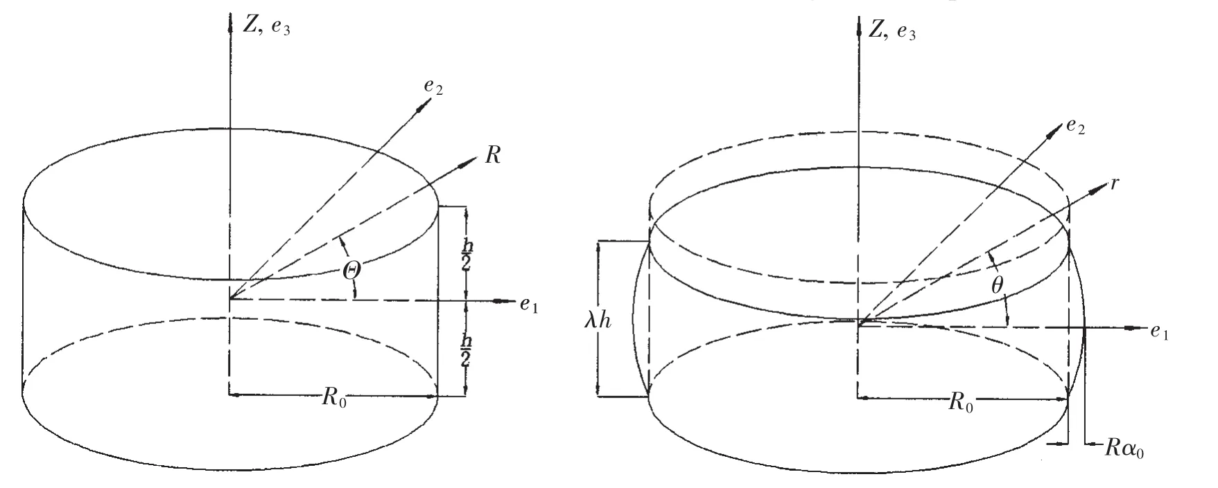
Fig.2 Undeformed and deformed configurations of the rubber pad
As mentioned above,two kinematic assumptions are adopted for this issue:planes parallel to the rigid plates remain plane and parallel and vertical lines become parabolic.Consequently,the transformation relation between the material and spatial coordinates are assumed to have the following forms:

The inverse transformation is:
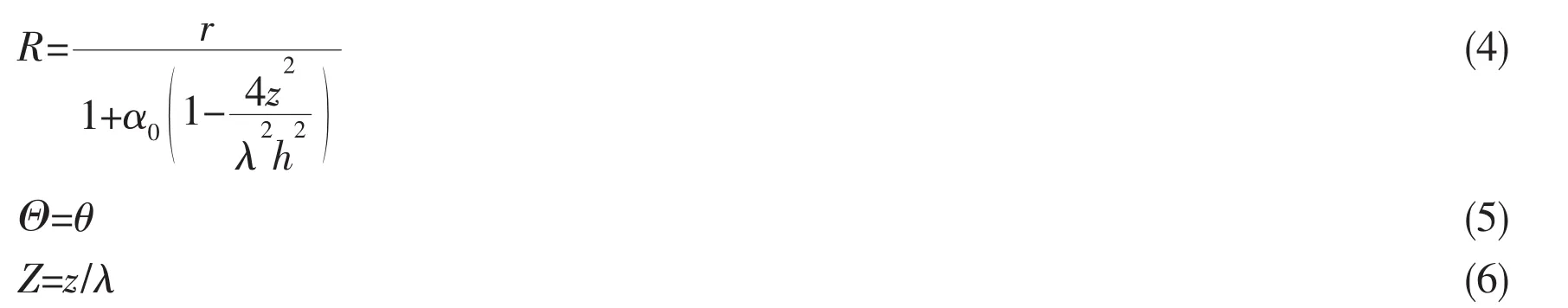
where λ is the length ratio in z direction and α0is the relative extension in radial direction at the mid-height of the rubber pad,regarded as a first order small quantity.
The incompressible condition requires that the volume of the rubber pad remains unchanged after deformation.If the second order small quantities are neglected,α0is found to be[3]:

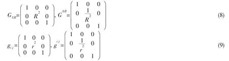
The covariant and contravariant components of the metric tensor of the material and spatial cylindrical coordinates are denoted as GAB,GAB,gij,gij,respectively.They have the following form:
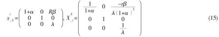
If the material and spatial coordinates are denoted byandthe deformation gradient F is defined by:

where giand GAare covariant base vectors of}and reciprocal base vectors ofThe left Cauchy-Green deformation tensor is[14]:

Similarly,the inverse of the left Cauchy-Green deformation tensor is:

where cijcan be calculated by the following equation:

Now substituting the productinto Eq.(1)and Eq.(4)by α,and define another parameter β,which is:

Utilizing Eq.(8),Eq.(9)and Eq.(11)through Eq.(15),we can get the contravariant components of B and B-1.


The Cauchy stress tensor of the incompressible hyperelastic material can be expressed by[14]:

where I is the metric tensor ofis the unknown hydrostatic pressure; ψ1and ψ2are the partial derivatives of the potential function with respect to the first and second invariant of B,respectively.That is,

For the incompressible Mooney-Rivlin material,

Utilizing Eq.(16)through Eq.(21)and the symmetry of the stress tensor,the nonzero components of the Cauchy stress tensor are:

The physical components of the stress tensor are identical to the above equations,except that Eq.(23)is substituted by the following equation:

In the following sections,the physical stress components are adopted in the derivation and indicated by σij.
2 Governing equations
Consider the equilibrium equation in r direction and the boundary condition:

where f1is equal to 0;r0is the radius of the rubber pad after deformation,which is a function of z.
Differentiate the Eqs.(22),(25)and(26),we obtain:

Once again take advantage of the assumption that α0is a first order small quantity,which means α and β are both first order small quantities.By neglecting the second order small quantities,Eqs.(29)through(31)become:

where,by using Eqs.(7)and(14),

Substituting Eqs.(32)through(35)into Eq.(27),we have:

3 Solution of the governing equations
Integrating Eq.(36)from r to r0and utilizing the boundary condition Eq.(28),we have:

where d is the compression amount between the upper and lower surface of the rubber pad.
From Eqs.(22)and(24),neglecting the second order small quantities,we obtain that:


In practice,the total force acting on the rubber pad and the total compression are of most concern.As a consequence,the effective compression modulus is,on average of the volume,defined as:

where the integral variable z has been transformed to Z to simplify the form of the integral.
Substituting Eq.(38)into Eq.(39),Ecbecomes:

From Eqs.(1)and(4),we have the relation:

Take advantage of the assumption that α is first order small quantity to simplify the formula.Using Taylor’s series,it can be proved readily that the mean value of the polynomial of1+()α in Z direction equals the polynomial of the mean value of1+()α and the error is second order small quantity,namely:

where k is an integer.Once again,from the incompressible condition,it can be derived that:

Substituting Eq.(41)through Eq.(43)into Eq.(40),we get:

At the beginning of the compression process,λ is approximately 1.0.Substituting 1.0 into Eq.(44)leads to:


and the initial modulus of elasticity is:

Moreover,for the incompressible Mooney-Rivlin material,the initial shear modulus is:
Then Eq.(45)reduces to:

where S is the shape factor of the circular layer.This equation is the same as the formula given by Gent and Lindley[3],which illustrates Eq.(48)is indeed the initial stiffness of the rubber component.
Based on Eq.(48),Lindley proposed a load-compression relationship for the circular rubber pad taking finite strain into consideration[11],which is:

where k is an empirical factor less than the theoretical value of unity and suggested to be 0.78 by Lindley.Both Eqs.(48)and(49)are adopted for comparison with Eq.(44)in the later discussion.
4 FEM solutions and discussion
The load-compression curves calculated by Eq.(44)were compared with the solutions of the nonlinear FEM program Abaqus,as well as the results of Eqs.(48)and(49).The FEM analysis is accomplished by using axisymmetric models and implicit algorithm.The incompressible Mooney-Rivlin material model was chosen and the hybrid stress element CAX4RH was adopted to avoid volumetric locking.Seven shape factors as shown in Tab.1 were considered with the same radius R0=200 mm.Four representative rubber materials from the engineering application,tabulated in Tab.1,were adopted in the calculation,indicated by Mat-1 through Mat-4.Among them,Mat-1 and Mat-2 have positive values of C2while Mat-3 and Mat-4 have negative values.Besides,the initial elastic modulus is much higher for Mat-2 and Mat-4.The compressive strain values,(d/h),in each calculation case are also shown in Tab.1.They are limited in a range so that the free surface is kept from contacting with the rigid plates.The maximal compression strain is 20%and it decreases with the increase of the shape factor S.

Tab.1 Material parameters and the total compression strain used in the calculatio n
Fig.3 and Fig.4 plot two typical load-compression curves for Mat-1 and Mat-3,with a shape factor of 0.25.It is seen that the results of Eq.(44)and the FEM fit very well while other formulae deviate from them gradually.The figures also show that Ecincreases with compres-sion.This tendency is more remarkable for Mat-1,i.e.,with a positive C2.It can be explained by subtracting Eq.(44)by Eq.(45),which leads to:

The coefficients of C1and C2are positive since λ is less than 1.As a consequence,the term of C1makes Ecincrease with compression as C1is always positive.However,the term of C2may have the same or opposite effect depending on its sign.

Fig.3 Load-deformation curves for Mat-1,S=0.25

Fig.4 Load-deformation curves for Mat-3,S=0.25

Fig.5 Effective compression modulus for Mat-1 at maximum compression

Fig.6 Effective compression modulus for Mat-2 at maximum compression
Similar phenomenon exists in other cases.The values of Ecat the maximum compression are plotted in Fig.5 through Fig.8.In these figures,Ecincreases significantly with the increase of S.This is because the first part of Eq.(44)is in proportion to the square of S.As expected,Eq.(44)provides the best fit to the FEM solution for all cases,irrespective of the material parameters and the shape factor.In a log-log coordinate,however,the accuracy of other formulae is not shown clearly.For this reason,the absolute value errors of all the formulae to the FEM solutions are shown in Fig.9 through Fig.12.Following observations are obtained:(1)The errors of Eq.(44)are very small and none is larger than 3.5%in all cases.(2)Eq.(48)has a low accuracy in most cases with a maximum error of 31.2%.(3)There is significant difference between the results of Eq.(49)with different values of k.When k=0.78,as suggested by Lindley,Eq.(49)provides a poor prediction of the rubber performance.When k=1,the effectiveness of Eq.(49)turned to be dominated by the sign of C2.The curves with negative C2have almost the same accuracy as Eq.(44).On the contrary,a positive C2still leads to a substantial error of over 20%.

Fig.7 Effective compression modulus for Mat-3 at maximum compression

Fig.8 Effective compression modulus for Mat-4 at maximum compression

Fig.9 Absolute value error of effective compression modulus for Mat-1 at maximum compression

Fig.10 Absolute value error of effective compression modulus for Mat-2 at maximum compression
From the above discussing,it can be seen that the formula derived in this paper,i.e.,Eq.(44),provides a good approximation to the real effective compression modulus of incompressible Mooney-Rivlin type circular rubber pad.Although small deformation hypothesis is used for simplification in the derivation,the formula is proved valid for the finite strain situation with various shape factors.Eq.(48)and Eq.(49)are not as effective as Eq.(44)for the low accuracy or the sensitivity of the material parameters or the uncertainty brought by the empirical coefficient.

Fig.11 Absolute value error of effective compression modulus for Mat-3 at maximum compression

Fig.12 Absolute value error of effective compression modulus for Mat-4 at maximum compression
5 Conclusions
The load-compression relationship of the incompressible Mooney-Rivlin type circular rubber pad bonded between rigid plates is derived in this paper.The derivation is based on two kinematics assumptions,i.e.horizontal planes remain plane and vertical lines become parabolic after deformation.Different from most previous research where linear elasticity is utilized,the hyper-elastic Mooney-Rivlin type material is considered and the derivation complies with the theory of continuum mechanics.
The theoretical solution,i.e.,Eq.(44),is obtained for this problem.The effective compression modulus is calculated on the average of the volume and the small deformation hypothesis is used for simplification.The comparison of the results to the FEM results shows the formula proposed has a very good accuracy in predicting the behavior of the circular rubber pad with various shape factors,even for the finite strain situation.
The advantages of Eq.(44)are:(1)It has a simple form to use and the accuracy is very high;(2)It is based on the Mooney-Rivlin type material rather than linear elastic material,which means a wider engineering application range;(3)It can provide a prediction of the loadcompression relationship of the rubber block for the finite strain situation.
[1]Morman K N,Pan T Y.Application of finite-element analysis in the design of automotive elastomeric components[J].Rubber Chem.Tech.,1988,61:503-533.
[2]Tsai H C,Lee C C.Compressive stiffness of elastic layers bonded between rigid plates[J].International Journal of Solids and Structures,1998,35:3053-3069.
[3]Gent A N,Lindley P B.The compression of bonded rubber blocks[J].Proceeding of the Institution of Mechanical Engineers,1959,173:111-117.
[4]Gent A N,Meinecke E A.Compression,bending and shear of bonded rubber blocks[J].Polymer Engineering and Sciences,1970,10:48-53.
[5]Kelly J M.Earthquake-resistant design with rubber[M].London:Springer,1993.
[6]Chalhoub M S,Kelly J M.Analysis of infinite-strip-shaped base isolator with elastomer bulk compression[J].Journal of Engineering Mechanics ASCE,1991,117:1791-1805.
[7]Chalhoub M S,Kelly J M.Effect of bulk compressibility on the stiffness of cylindrical base isolation bearings[J].International Journal of Solids and Structures,1990,26:734-760.
[8]Koh C G,Kelly J M.Effects of axial load on elastomeric isolation bearings[R].Report no.UCB/EERC-86/12,Berkeley:Earthquake Engineering Research Center,University of California,1987.
[9]Koh C G,Kelly J M.Compression stiffness of bonded square layers of nearly incompressible material[J].Engineering Structures,1989,11:9-15.
[10]Tsai H C,Pai W J.Simplified stiffness formulae for elastic layers bonded between rigid plates[J].Engineering Structures,2003,25:1443-1454.
[11]Lindley P B.Load-compression relationships of rubber units[J].J Strain Anal.,1966,1:190-195.
[12]Klingbeil W W,Shield R T.Large-deformation analyses of bonded elastic mounts[J].Z.Angew.Math.Phys,1966,17:281-305.
[13]Hill J M.A review of partial solutions of finite elasticity and their applications[J].International Journal of Non-Linear Mechanics,2001,36:447-463.
[14]Huang Z P.Fundamentals of continuum mechanics[M].Beijing:Higher Education Press,2011.

- 船舶力學(xué)的其它文章
- Jacket Effects on Heave,Roll and Pitch Motions of a New Floating Deep-draft Semisubmersible Concept
- Convergence Method for Hydrodynamic Force on Surface Structures with Oblique Boundaries
- Influence of Excitation Location on Sound Radiation of a Simple Duct Excited by Sound Source
- Two-dimensional Eulerian-Lagrangian Modeling of Shocks on an Electronic Package Embedded in a Projectile with Ultra-high Acceleration
- Mechanical Behavior of Flexible Jumper Installation in 3D Space
- Characteristics of Tendon Vortex Induced Vibrations Influenced by Platform Motion