基于電壓影響下圓偏振激光束的特性
2018-03-01 10:00:11郝蕊蕊趙新未焦新兵
光學(xué)儀器 2018年1期
郝蕊蕊, 趙新未, 潘 倩, 柏 雪, 焦新兵
(1.上海理工大學(xué) 光電信息與計算機工程學(xué)院, 上海 200093;2.上海理工大學(xué) 上海市現(xiàn)代光學(xué)系統(tǒng)重點實驗室, 上海 200093;3.上海理工大學(xué) 教育部光學(xué)儀器與系統(tǒng)工程研究中心, 上海 200093)
Introduction
Garnet is widely researched and used because of its excellent optical,electrical and magnetic properties[1- 4].The polarization plane of a linearly polarized laser beam can be rotated through garnet or reflected from the garnet surface.The garnet surface is linearly proportional to the magnetic field in the laser propagation direction,known as the Faraday effect and the Kerr effect.In our previous work,the interfaces of garnet and graphite can be generated as a function of external direct current(DC) voltage,and the splitting effect is investigated[5- 9].The changes in optical properties of a circularly polarized laser beam attribute to external conditions.In this paper,the optical properties of a circularly polarization laser beam reflects from a aluminum film,one weakly absorbing media,are researched.The optical position and optical polarization properties of the laser as a function of external DC voltage are researched by slit beam profiler and polarimeter.The optical shift of the circularly polarized laser beam and polarization properties imply a good approach for the design and analysis of optical devices.
1 Experimental principle
Figure 1 is a schematic diagram of the experimental setup.A continuously laser beam with a wavelength of 1 550 nm,with a intensity of 18 mW,goes through Thorlabs mounted zero order compound WPQ10- 1550 wave plate,then turns into circularly polarized laser.The circularly polarized laser beam goes into a prism vertically,and reflects from an aluminum film on the oblique side of the prism.After that the circularly polarized laser beam arrives at the Thorlabs CCM1- BS015 non polarized beam splitter.The laser beam is splitted into two optical laser beams,one beam arrives at the Thorlabs BP209- IR slit beam profiler and another one arrives at the Thorlabs PAX5710 polarimeter.Garnet(Granopt Co.,Ltd.,GLB1550,2 mm×2 mm×0.39 mm) and graphite(10 mm×10 mm×0.3 mm) are fixed under the aluminum film of the prism.A pair of copper electrodes are in contact with graphite at a distance of 1 mm.The polarization characteristics of the laser beam are measured by applying a DC voltage to the copper electrode.In order to character the optical spot conveniently,it is assumed that,thezaxis is in the perpendicular direction of the garnet,theyaxis is in the plane of the garnet and along the propagation direction of the laser beam and theyaxis is perpendicular to the direction of the propagation direction of the laser beam.The optical spot energy distribution of the circularly polarized laser beam are measured by Thorlabs BP209- IR slit beam profiler.
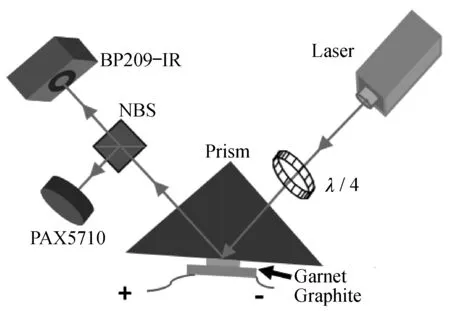
Fig.1 Schematic of the experimental setup
2 The change of optical position
To evaluate the optical spot position of the laser beam,which reflects from the aluminum film on the prism,the optical spot position and optical spot energy distribution of the circularly polarized laser beams as a function of external DC must be measured.In this experiment,the position of the maximum energy of the circularly polarization laser beam is used to describe the position of the optical spot,as the initial state of 2- dimensional and 3- dimensional optical spot energy show Gaussian distribution shown in Fig.2.
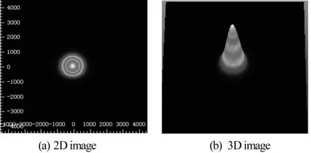
Fig.2 2- dimensional and 3- dimensional optical spot energy distribution
As the optical spot position can be described by the maximum energy of the circularly polarized laser beam.Figure 3 shows the measuring and polynomial fit of the optical spot position when the external DC value changes from 0 to 2.5 V.Thexposition of the circularly laser beam moves from -45 μm to -95 μm when the external DC voltage increases from 0 to 2.5 V as shown in Fig.3(a).The polynomial fit fomular of thexposition of the circularly laser beam can be described by equation (1).A1,B11,B12are constant parameters and the parameter values are shown in table 1.
y1=A1+B11×x+B12×x2
(1)
Theyposition of the circularly laser beam moves from 35 μm to 75 μm when the external DC voltage increases from 0 to 2.5 V as shown in Fig.3(b).The polynomial fit of theyposition of the circularly laser beam can also be described by equation (2).A2,B21,B22are constant parameters and the parameter values are shown in table 2.
y2=A2+B21×x+B22×x2
(2)
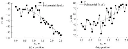
Fig.3 Measuring and polynomial fit of optical position of the circularly polarized laser beam as a function of external DC voltage
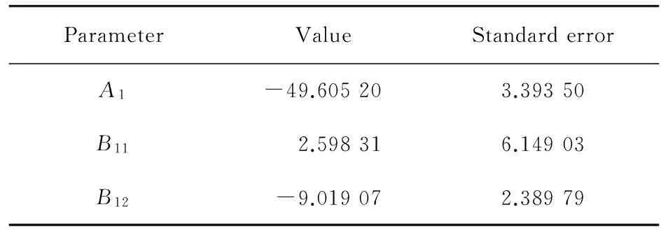
ParameterValueStandarderrorA1-49.605203.39350B112.598316.14903B12-9.019072.38979
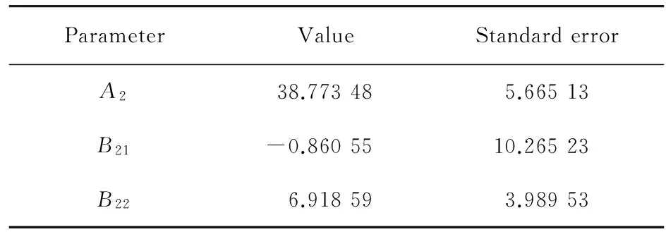
Tab.2 The parameter values of the polynomial fit formula of y position
From table 1 and table 2,the value ofB11is more than zero,and the value ofB21is less than zero,so it can be seen that thexposition of the circularly polarized laser beam moves toward to thexnegative axis,while theyposition of the circularly polarized laser beam moves toward to theypositive axis.So the optical spot position of the circularly polarized laser beam can be controlled by external DC voltage,as shown in Fig.3.
Figure 4 shows the optical energy distribution of the circularly polarized laser beam at different external voltage.The optical energy intensity in thexposition increase from 63.7% to 76.8%,when the voltage increases from 0 V to 2.5 V,while the optical energy intensity in theyposition decrease from 50% to 46.6%.So,the optical energy intensity in thexposition andyposition have different change trend when the external voltage change.
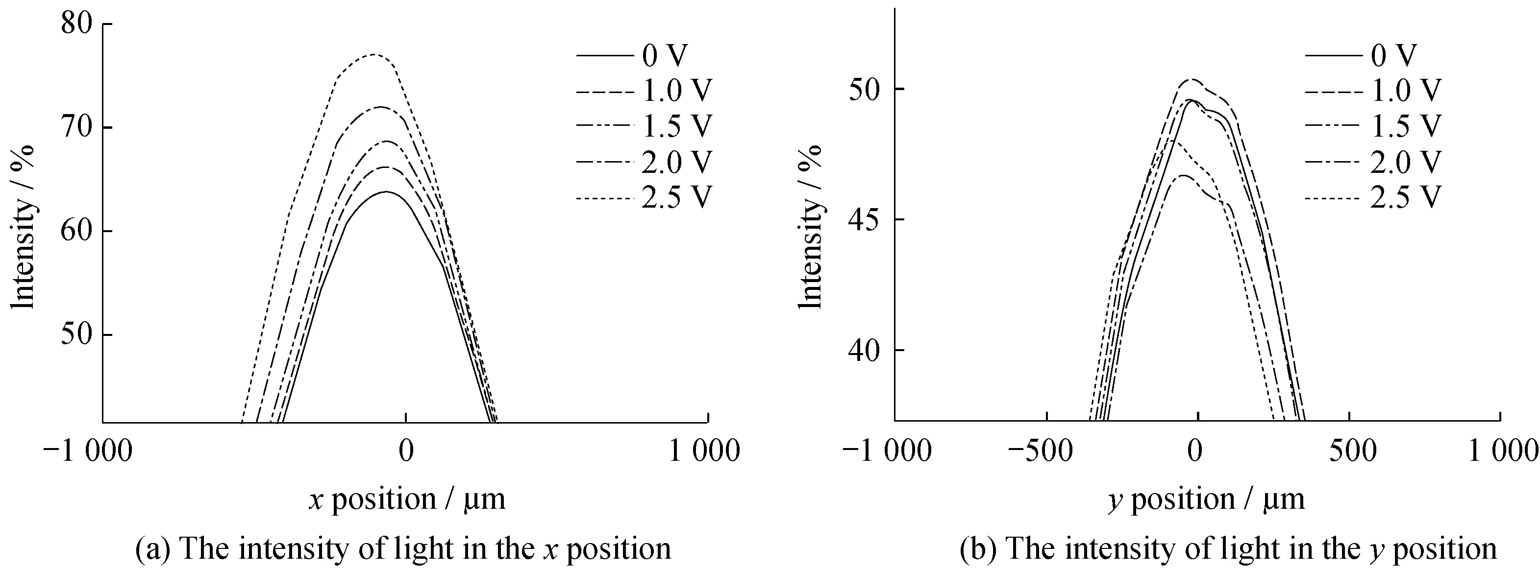
Fig.4 Optical energy distribution of the circularly polarized laser beam at different external voltage
3 Polarization properties of the circularly laser beams
The optical spot positions and the optical energy in thexposition and theyposition of the circularly polarized laser beam show different trends when the external DC voltage value increases from 0 V to 2.5 V.The optical polarization properties of the circularly polarized laser beam also be researched as a function of the external DC voltage value.The degree of polarization may change on propagation precessure in free space[10- 11]and dependent on the spatial location[12- 14].Figure 5 illustrates the relationship between the Stokes parameterS1,S2,S3,DOPof the circularly polarized laser beam and the external DC voltage value.The Stokes parameters ofS1,S2,andS3can describe all the polarization states of electromagnetic waves[15- 16].S1is the intensity difference between horizontally polarized laser beam and vertically polarized laser beam,S2is the intensity difference between +45°polarized laser beam and -45°polarized laser beam,andS3is the intensity difference between right- circularly polarized laser beam and left- circularly polarized laser beam.The degree of linear polarization(DOLP),degree of circular polarization(DOCP) and degree of polarization can be described by Stokes parameters:
The Stokes parametersS1of the circularly polarized laser beam is 0.6,and basically unchanged when the the external DC is less than 1.0 V,then,theS1changes from 0 to 0.6 when the external DC voltage change from 1.0 V to 2.5 V.The Stokes parametersS2of the circularly polarized laser beam changes from 0 to -0.9,when the external DC voltage change from 0 V to 1.5 V,while,the variation range ofS2is small.The Stokes parametersS3of the circularly polarized laser beam decreases from 0.8 to 0,when the external DC voltage change from 0 V to 2.5 V.TheDOLP,DOCPandDOPof the circularly polarized laser beam can be got from equations (3),(4),(5).TheDOLPandDOCPcan be changed,while theDOPbasically unchange,when the external DC voltage changes from 0 V to 2.5 V.
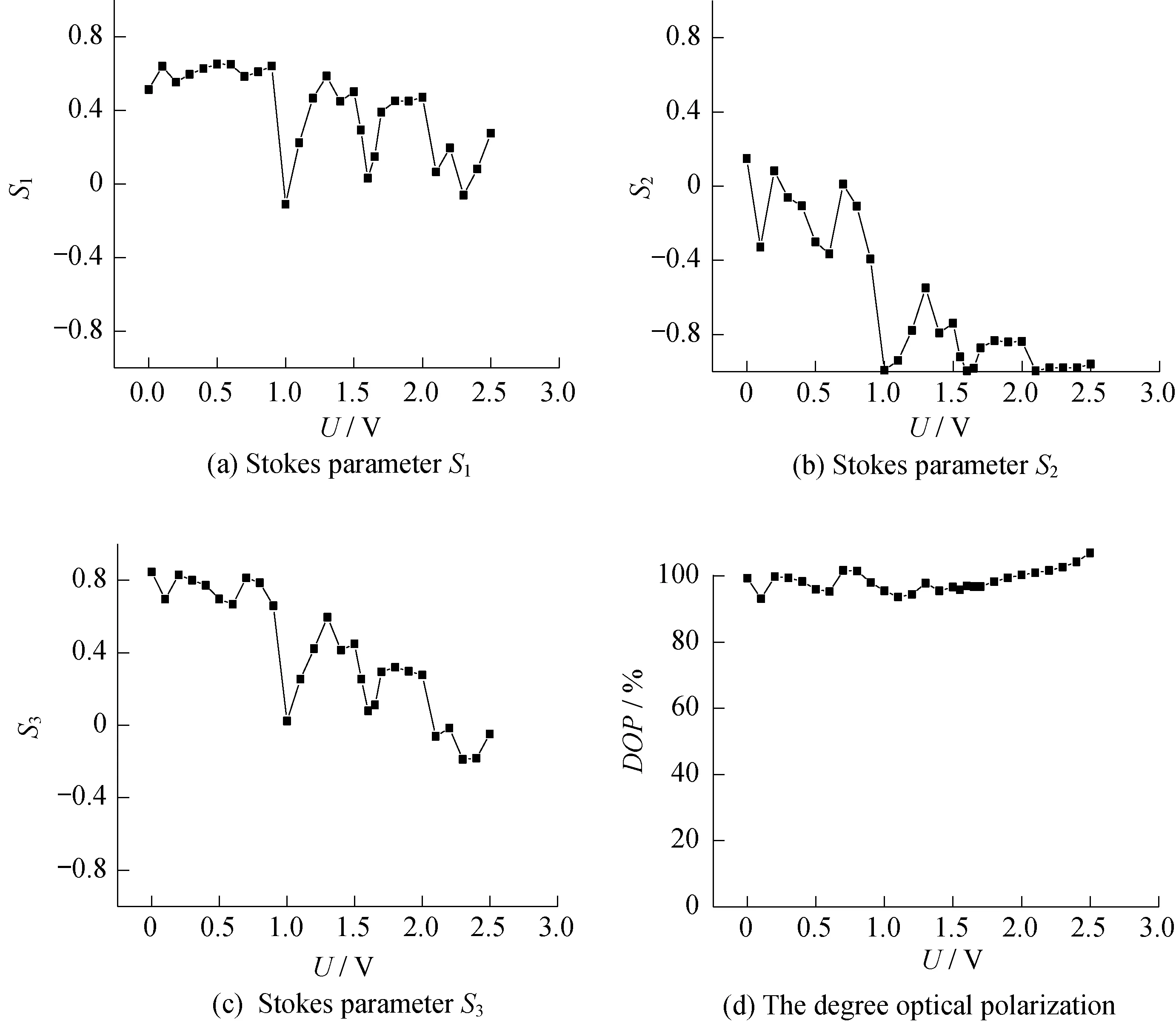
Fig.5 Polarization properties of the circularly laser beams reflect from aluminum film on the prism as a function of DC voltage
4 Conclusion
In conclusion,optical spot position and the polarization properties of circularly polarized laser beam reflected from an aluminum film as a function of the external direct current voltage are measured by a slit beam profiler and a polarimeter.The measured and polynomial fit results show that thexandyoptical position of circularly polarized laser moves from -45 μm to -95 μm and moves from 35 μm to 75 μm.The optical energy intensity in thexposition andyposition have different change trend when the external DC value changes from 0 V to 2.5 V.The Stokes parameter ofS1,S2,andS3can be changed,while theDOPof the laser beam basically do not change.The optical shift of the circularly polarized laser beam and polarization properties imply a good approach for the design and analysis of optical devices.
[1] SAITO S,FUJII Y,YOKOYAMA K,et al.The laser current transformer for EHV power transmission lines[J].IEEE Journal of Quantum Electronics,1966,2(4):147.
[2] RIPKA P.Electric current sensors:a review[J].Measurement Science and Technology,2010,21(11):112001.
[3] YI B,CHU B C B,CHIANG K S.Magneto- optical electric- current sensor with enhanced sensitivity[J].Measurement Science and Technology,2002,13(7):N61.
[4] LI S G,YANG C X,ZHANG E Y,et al.Dynamic performance of magneto- optical Bi- substituted rare- earth iron garnet[J].Chinese Optics Letters,2005,3(1):38-41.
[5] JIAO X B,NGUYEN T G,QIAN B,et al.Faraday Effect sensor redressed by Nd2Fe14B biasing magnetic film[J].Optics Express,2012,20(2):1754-1759.
[6] JIAO X B,ZHAO X W,BAI X,et al.Beam splitter driven by garnet- graphite interface effect[J].Physica Status Solidi A,2017,214(8):1700103.
[7] JIAO X B,BAI X,ZHAO X W,et al.Optical beam shift induced by direct current[J].Physica Status Solidi A,2017,214(10):1700265,doi:10.1002/pssa.201700265.2.
[8] ZHU X Y,HUANG Z Y,WANG G H,et al.Ultrasonic detection based on polarization- dependent optical reflection[J].Optics Letters,2017,42(3):439-441.
[9] JIAO X B,MA Y,MA L X,et al.Polarization properties of garnet and groove films on garnet in the transmission and reflection modes[J].Optics Express,2014,22(2):1673-1679.
[10] PROVENZIANI D,CIATTONI A,CINCOTTI G,et al.Stokes parameters of a Gaussian beam in a calcite crystal[J].Optics Express,2002,10(15):699-706.
[11] FLOSSMANN F,SCHWARZ U T,MAIER M,et al.Stokes parameters in the unfolding of an optical vortex through a birefringent crystal[J].Optics Express,2006,14(23):11402-11411.
[12] JAMES D F V.Change of polarization of light beams on propagation in free space[J].Journal of the Optical Society of America A,1994,11(5):1641-1643.
[13] ZHAO X H,YAO Y,SUN Y X,et al.Condition for Gaussian Schell- model beam to maintain the state of polarization on the propagation in free space[J].Optics Express,2009,17(20):17888-17894.
[14] VERMA M,SENTHILKUMARAN P,JOSEPH J,et al.Experimental study on modulation of Stokes parameters on propagation of a Gaussian Schell model beam in free space[J].Optics Express,2013,21(13):15432-15437.
[15] MEI Z R.Generalized stokes parameters of three- dimensional stochastic electromagnetic beams[J].Optics Express,2010,18(22):22826-22832.
[16] CHEN P C,LO Y L,YU T C,et al.Measurement of linear birefringence and diattenuation properties of optical samples using polarimeter and Stokes parameters[J].Optics Express,2009,17(18):15860-15884.
猜你喜歡
中國交通信息化(2022年6期)2022-08-30 09:20:52
上海理工大學(xué)學(xué)報(2021年3期)2021-07-20 08:04:22
學(xué)生導(dǎo)報·高中版(2021年19期)2021-06-28 01:20:03
科技風(2018年19期)2018-05-14 05:13:39
科技創(chuàng)新與應(yīng)用(2017年11期)2017-04-27 20:47:28
鐵道通信信號(2016年3期)2016-06-01 12:10:18
小說月刊(2015年3期)2015-04-19 07:05:54
百科知識(2014年11期)2014-06-10 05:47:57
中學(xué)理科園地(2014年1期)2014-04-29 00:44:03
上海理工大學(xué)學(xué)報(2011年6期)2011-03-20 13:53:59